What is Percentage Impedance & Calculate Percentage Impedance?
“The percentage impedance is nothing but a measure of the volt drops when the transformer in on full load due to the winding resistance and leakage reactance expressed as a percentage of the rated voltage.” Also in other words it is a percentage of the ratio between the full load short circuit terminal voltage to nominal voltage of the transformer. It is denoted by %Z. Z is called Impedance.
Secondly, it defines the voltage regulation of the transformer because of maximum voltage regulation is directly proportional to the p.u impedance of the transformer. So a high p.u impedance will reduce the short circuit level and on the other it will result in poor voltage regulation. And a low p.u impedance will result in higher short circuit level and good voltage regulation.
You May Like:
- Why transformer Rating in KVA exact answer
- Why VFD Duty Motor Frame Size is Higher Than Normal Motor
- Why we should not give dc supply to Transformer
- Why Zig-Zag Winding Transformer Used
- 7 Purpose of NGR Neutral Grounding Resistor Transformer & Generator
Percentage Impedance Calculation:
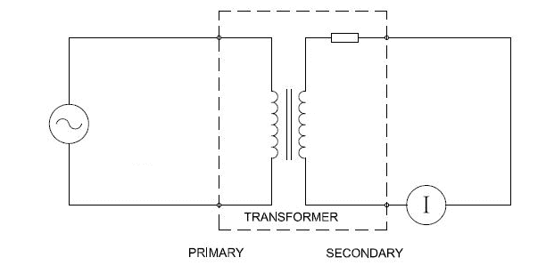
Take a single transformer. The primary of the transformer will be connected with the variable AC voltage source (variac) and the secondary terminal of the transformer will be shorted as shown in the figure. The primary of the transformer will be energized from low voltage level. Upon increasing the voltage across the primary, the secondary current starts increasing. Rise the voltage in primary until to reach rated secondary current in secondary winding. Now measure the voltage across the secondary terminal. This is the voltage drop due to the internal resistance and reactance of the transformer.
Percentage Impedance Formula:
Significance of percentage impedance:
- Increasing % Z or percentage impedance reduces the short circuit current and
- High Value of %Z percentage impedance causes more voltage drop and poor voltage regulation. Finally, transformer delivers less efficiency.
- The %Z is used to design a protection switchgear. Typically, it is used to calculate maximum level of fault current. So that, we can design a switch gear to withstand that maximum level of fault current.
Let see an example.
The short circuit current can be calculated from the ratio of full load current to the percentage impedance value. Thus, the formula of short circuit current using percentage impedance,
Transformer rating
- 75 kVA
- 240 V secondary
- 5% impedance
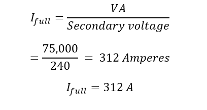
Calculate the full load secondary current
Therefore, the short circuit current Isc is
[wp_ad_camp_2]
Therefore, the maximum short circuit current is almost 20 times of its full load current.
So that you can design or choose your switchgear to withstand at 20 times of its full load current for the transformer of 5% percentage Impedance. The rating is called kAIC. i.e if you have less than 5% i.e 2.5 % means the short circuit current still increase and again you have to go for high rating of kAIC i.e 40 times for 2.5 %Z.
Also see:
- Distribution Transformer & Power Transformer
- Droop CT – Droop Current Transformer
- Equipotential shielding of current transformer
- How Induction Motor as a rotating Transformer
- Merz Price Differential Protection for Transformer
- Reason For Transformer Core Saturation
- Significance of Leakage Reactance of Transformer
- Three Phase Transformer Vector Grouping Significance of Vector Grouping
- Transformer Bushing Operating Principle
- Transformer Core Construction Details
- Transformer Name Plate Details Fully Explained


