What is an open circuit or no-load test?
The Open circuit test is used to find the performance characteristics of the transformer at no-load condition. This test should be conducted at rated flux condition i.e, rated voltage and frequency.
Why does Open Circuit Test Need?
- To find out the core loss or constant loss at rated voltage and rated frequency in the transformer.
- To find out the shunt branch or no-load branch parameters such as Ro and Xm.
- To find out the turns ratio of the transformer.
How to do Open Circuit Test:
An open circuit is carried out at a rated voltage on low voltage winding side with the open-circuited high voltage winding. It is carried out on a low voltage side because the rated voltage can be easily possible on low voltage side by varying the autotransformer.
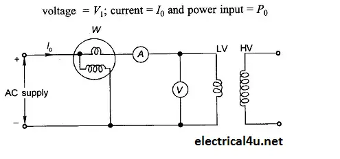
A voltmeter, an ammeter and wattmeter are connected on a low voltage side. All three instrument readings are recorded. No-load or exciting current is only 2-5% of full load can be measure with the greater accuracy than the accuracy of high voltage side. Wattmeter reads core losses of the transformer because no-load losses are very less.
Equations to find out the parameters:
Pi = Voc x Io x Cosφ
Where,
Pi = core loss
Voc=open circuit voltage
Io no-load current
Cosφ = No load power factor
Hence, the No-load Power factor Cosφ0 = Pi / (Voc x Io)
From the phasor diagram,
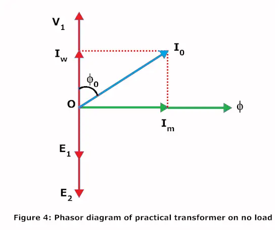
Ii = Iw
Here Ii = Io x cosφo
Im = Io x sinφo
Core loss resistance Rc = Voc / Ii
Magnetizing reactance Xm = Voc / Im

 Chart – Transformer Wire Amperage Table")


