What is 4 to 20mA
4 to 20 mA or 0 to 20mA uses in the automation for the current loop function. Mostly, almost 90% of the industry is depending on automation. For process control, the control circuit (Example: PLC or DCS) sends 4 to 20 mA current as a reference signal (which is created by a user or automated device) to the driver circuit (Example: Field Instruments such as VFD, pneumatic Value) receives and the same operation the field instruments as per reference signal.
The driver circuit also gives the feedback signal of 4 to 20mA with respect to the reference signal. Here driver circuit and controller circuit paired each other.
i.e Now the controller gives 6mA means, the driver circuit operates the field devices until to reach 6 mA feedback signal. Here controller compares the input signal and feedback single; if the final error becomes zero then the controller considers the target is reached. In industry, 4 to 20mA or 0 to 20mA current loop ensure the system is automated.
In this article we are going to discuss about how 4 to 20mA or 0 to 20 mA current loops is working and how to calculate the voltage of 4 to 20mA signal.
Let us assume, we have a VFD (Variable Frequency Drive), Motor and DCS (Distributed Control System); Motor is connected with VFD and the VFD’s controller is connected with DCS. DCS is operated by a user.
Motor is operated between 0 to 1490 RPM it means (0 to 50/60 Hz). Here, DCS and VFD are programmed with the motor data such as 4 mA for 0 RPM for minimum reference value and 20mA for 1490 RPM (Maximum reference value). Exactly 0 to 100% (0 for 4mA and 100% for 20mA RPM).
User will send the reference in terms of percentage and this reference is converted into equal amount of current.
i.e if user request DCS to operate a motor at 50% of the speed means, the DCS controller generates 12 mA (4mA +8 mA) of current and send it to input to VFD.
The VFD generate output to operate a motor at 745 RPM (50%), Now our VFD drive gives the speed feedback status to DCS in terms 0 to 20 mA. This is how the current loop is formed. Or in simple sentence
DCS Send 4 to 20mA input reference to VFD
VFD Send 4 to 20 input DCS as Feedback
According to the user request, the field motor operates through DCS and VFDs with the help of the current loop.
Why 4 to 20mA not 0 to 20mA:
Many automation manufacturers use 4 to 20 mA current loop system instead of 0 to 20mA. Since, during the external or internal fault condition, we cannot able to identify the fault location where the cable carries 0 mA.
For an example, consider a cable got open circuited, then, current flow through the circuit will become 0mA. In case, If we inject the current through cable is 0mA as minimum current means we cannot able to predict the circuit healthy condition. If we inject 4 mA as minimum current means, during the fault condition we get 0mA at the receiver end.
To check healthiness of the circuit and trace the fault condition in the system we should prefer for 4 to mA.
What is the voltage of 4 to 20mA current:
For calculating voltage of the 4 to 20mA, we can use Ohm’s Law. As law stated,
Voltage= Current* Resistance. In many automation devices, the 4 to 20mA is converted into 10Voltage DC. Example: ABB
i.e current reference is 8mA
V= I*R
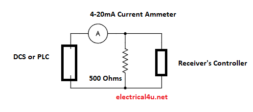
10= 0.02*R => R=10/0.02 = 500 Ohms
Hence, 500 ohms of resistance will be connected across the receiver. The voltage will be varied according to the current reference,
For 10mA current input => V=500*0.01 => 5 Volts
For 4mA Current input => V= 500*0.004 => 2 Volts.
In such way the voltage can be varied through the resistance connected across.


