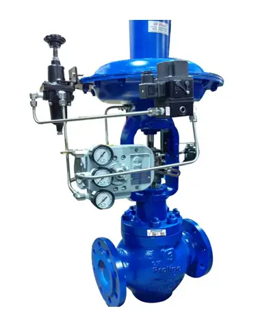
What is CONTOL VALVE
A control valve is used for control the flow directed by a signal from the controller. This controls the process quantities such as pressure, temperature flow and level.
In automatic control the control valve is termed as a FINAL CONTROL ELEMENT.
Equipments required for calibration
- Controller for signal
- I/P(current to pressure transducer)
- Positioner
Controller for signal
The electrical Signal will be generated from the DCS or Multifunction calibrator as a 4-20 mA will de transmitted to I/P converter.
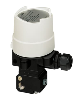
I/P (current to pressure transducer)
The current to pressure transducer is a device which will convert the current signal 4 to 20 mA into pneumatic output as 3 to 15 psi,This I/P provides a repeatable,accurate of converting electrical signal to pneumatic pressure in control system.
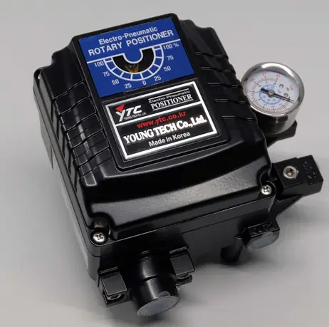
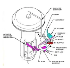
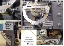
Positioner
Positioner is the main device for calibration of control valve.
Positioner is a pneumatically operated valves which received the signal from the controller and to travel the valve for open and close operation.
A Pneumatic signal(3-15 psi) is supplied for the positioner then positioner will compares the valve stem position with the signal generated by the controller. If the valve stem is in incorrect position the positioner will either increase or decrease the air actuator until the valve stem retain to correct position .
Procedure for calibration
Step 1: Initial check the position of the valve open/ close then stroke , check the air pressure 4 kg/cm²
Step 2: Initially zero to wants to be check the valve by Give the 4 mA through the MFC in the I/P and check the fully valve closed position if not then adjust in the Positioner for fully closed the valve and also check the I/P output and the air pressure.
Step 3: Give the 8 mA through the MFC in the I/P and check the valve opening for 25 percentage if 25% opens ok if not then adjust in the Positioner for the 25 % to open the valve also check the I/P output and the air pressure.
Step 4: Give the 12 mA through the MFC in the I/P and check the valve opening for 50 percentage if 50 % opens ok if not then adjust in the Positioner for the 50 % to open the valve also check the I/P output and the air pressure
Step 5: Give the 16 mA through the MFC in the I/P and check the valve opening for 75 percentage if 50 % opens ok if not then adjust in the Positioner for the 50 % to open the valve also check the I/P output and the air pressure
Step 6: Give the 20 mA through the MFC in the I/P and check the valve opening for 75 percentage if 50 % opens ok if not then adjust in the Positioner for the 50 % to open the valve also check the I/P output and the air pressure
Step 7: After completion of the calibration the calibration records are to be recorded


