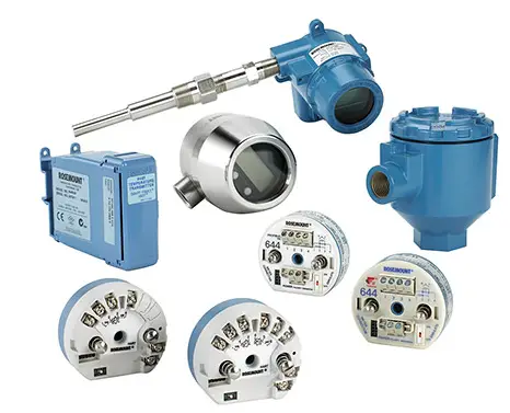
Temperature Transmitter
Temperature transmitter is a device used for to convert RTD and thermocouple signals into 4-20 mA output signal for connecting to DCS or PLC for running the industry in a efficient mode.
Use of Temperature Transmitter
In many remote places and inside heavy machineries such as turbine ,boiler generators etc, temperature to be monitored but from the temperature measuring devices thermocouple and RTD are only able to produce very small signals if this signals are connected directly to DCS there will be some signal loss for to reduce this signal loss we are connecting the temperature transmitter for amplify and transmit through the copper type signal cables.
Equipment’s required for calibration
- Temperature transmitter,
- 24Vdc power supply,
- Decade resistance box,
- Digital Multimeter,
Decade resistance box
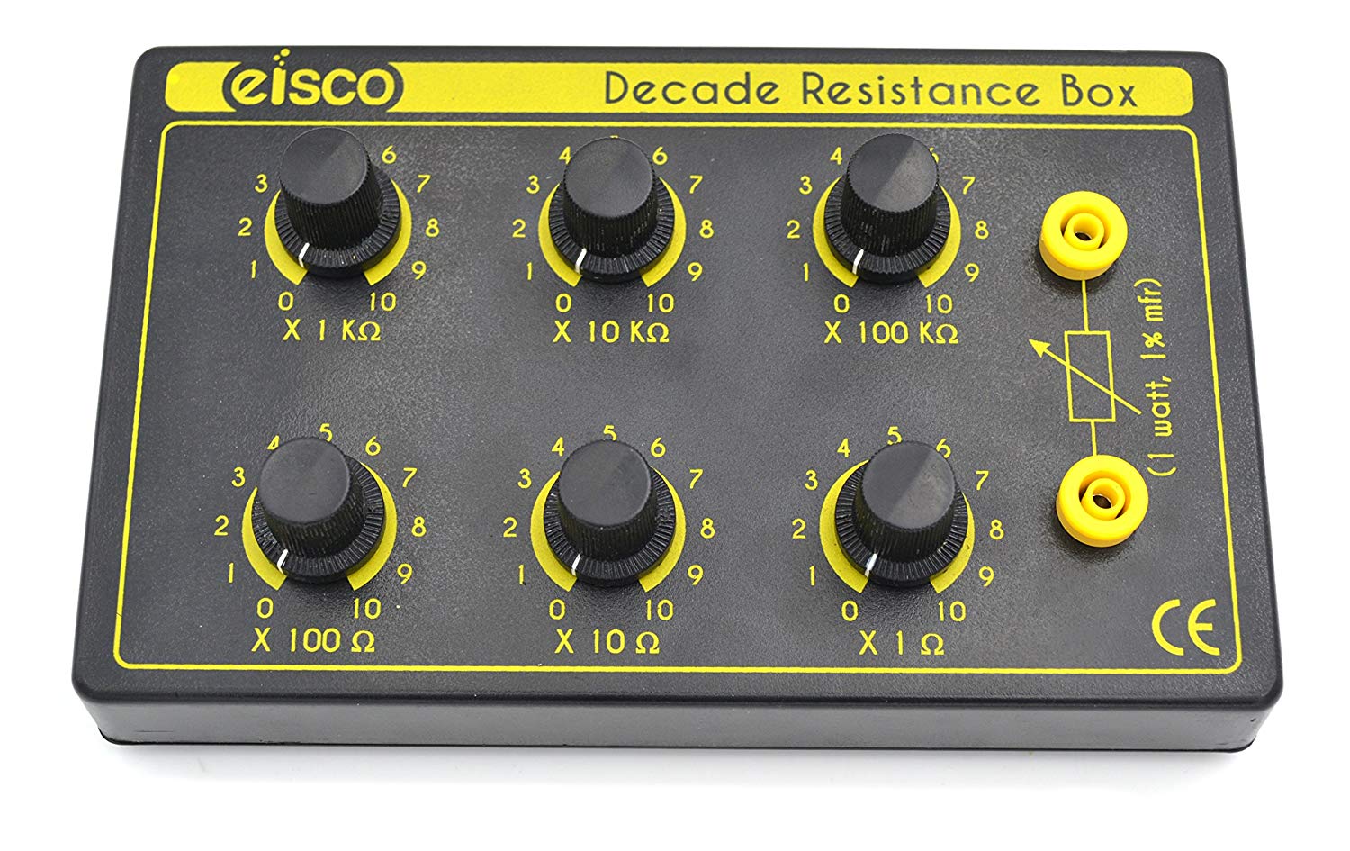
The decade resistance box is a test equipment made of a resistance, inductance, and capacitance which can be increased the values by switching for the contact input and output throughout the series for components.
This device is usually consists of dials and adjustable knobs for operated in circuit and without any power source.
Calibration procedure
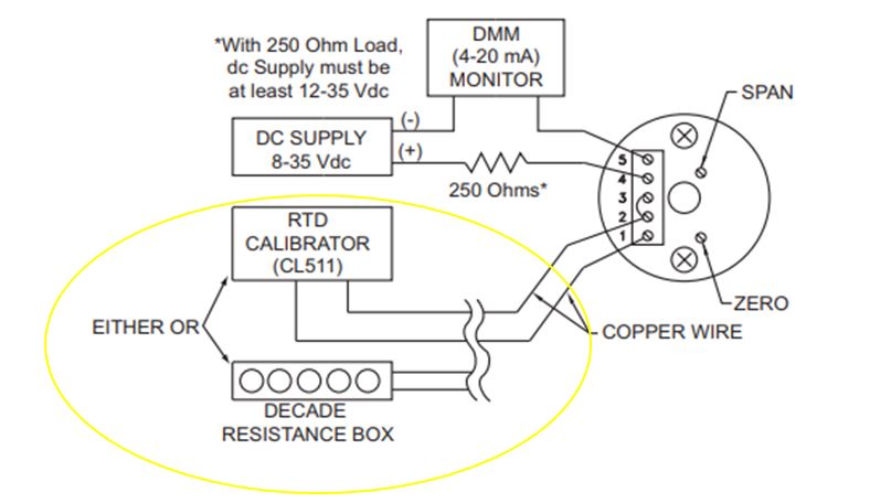
Step 1: Temp transmitter is calibrated using Master Decade resistance box or Multi-Function Calibrator
Step 2: Decade resistance box is for Resistance source & Multi-Function Calibrator is for millivolt source.
Step 3: Connect the field input connections to temp tx from Decade resistance box/MFC (resistance/millivolt) & 24 Vdc supply to output terminals.
Step 4: For Zero calibration, apply the resistance or millivolt (RTD/TC) as per standard RTD/TC chart then check the milliamps output in output terminals using multi-meter in series if the transmitter output is 4mA then go for the span calibration. If Tx output is showing error then adjust the zero knobs until it gives 4 mA output. If adjusted also not gives 4 mA want to replace the new transmitter.
Step 5: For Span calibration, apply the resistance or millivolt (RTD/TC) as per standard RTD/TC chart then check the milliamps output in output terminals using multi-meter in series if the transmitter output is 20mA then go for the span calibration. If Tx output is showing error then adjust the span knob until it gives 20 mA output. If adjusted also not gives 20 mA want to replace the new transmitter
Step 6: For example: Pt. 100 RTD Temperature Transmitter range is 0 to 600 deg Then for 0 ºC temp Resistance output is 100 ohms & 4 mA Then for 600 ºC temp resistance output is 313 ohms & 20 mA The calibration records are Recorded.


