What is Differential Pressure Transmitter
The Differential pressure transmitter is a common measuring instrument in industries and domestic applications such as flow, level, density etc. the most commonly used for level and flow.
The DP flow measurement is the most common application for using the DP transmitter. While fluid is flow through the pipe it is possible to calculate the flow rate.
Differential pressure flow meters have a primary and secondary element. The primary element is designed for to produce differential pressure while the flow is increased.
Secondary element of differential pressure transmitter is used to measure the primary element pressure accurately as possible even when fluid pressure changes, temperature.
Variable head flow meter operate on the principle that a restriction in the line of a flowing fluid, introduced by the orifice plate or venture tube or elbow, produces a differential pressure across the restriction to the flow rate.
The output signal from the DP transmitter is 4-20 mA.

Equipments required for calibration
- Hand pump
- Pressure calibrator
- Digital multimeter
- 24Vdc power supply
Hand pump,
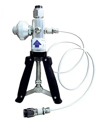
The hand pump is used for giving the external pressure source for transmitter.,
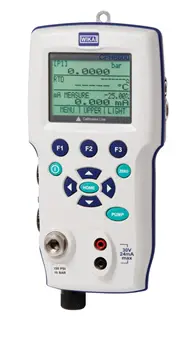
Pressure calibrator.
Pressure calibrator is used for to compare the output pressure with the actual pressure.
Digital Multimeter
The digital multimeter is used for measuring the current.
Power supply.
24V dc is used for switch on the power supply for transmitter.
Calibration Procedure
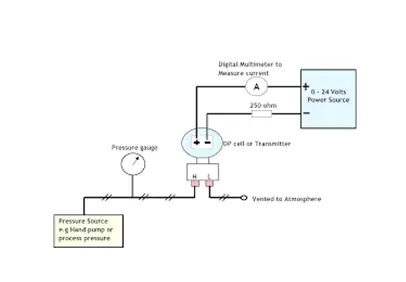
Step 1: Process Calibrator is connected in the Hand held pump (low or high range) and pump output is connected to the H side of differential pressure transmitter & L side of Transmitter is at constant pressure (atmospheric) to be calibrated.
Step 2: Switch ON the processor calibrator and pressure transmitter.
Step 3: Set the unit in the process calibrator according to the pressure transmitter.
Step 4: For zero calibration, ensure the process calibrator reading is Zero then see the pressure transmitter reading in milli amps(4 mA),if it is giving correct output then go for the span calibration otherwise adjust the Zero knob until it gives 4 mA output. If adjusted also not gives 4 mA want to replace the new transmitter
Step 5: For Span calibration, raise the pressure through hand pump up to transmitter high range by seeing the process calibrator. Then you check the Pressure transmitter output in milli amps (20 mA). If it is giving correct output then ok, suppose output showing error then adjust the Span knob until desired output. If adjusted also not gives 20 mA want to replace the new transmitter.
Step 6: For example, pressure transmitter range is 0 to 10 kg/cm2Then at 0 mmwc pressure output is 4 mA & At 2500 mmwc pressure output is 20 mA.
Step 7: The calibration records are to be Recorded


