What is Thyristor?
The thyristor is a device having three or more PN junctions. Most commonly used thyristor is SCR (Silicon Controlled Rectifier)
The thyristor is classified into different types; they are SCR, DIAC, TRIAC, and UJT.
Here we are going to discuss about Silicon Rectified Rectifier (SCR)
Silicon controlled rectifier (SCR)
SCR was developed by a team of power engineers lead by Robert N Hall and communicated by the frank wbill cutzwiller in 1957.
Construction of SCR Silicon controlled rectifier:
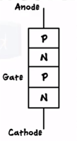
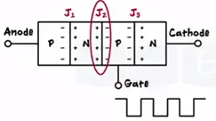
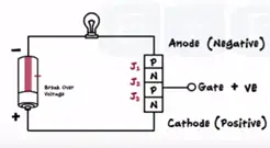
SCR is a device having structure PNPN regions. The two structures NPN and PNP are combined together form PNPN structure.
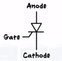
The symbol of SCR is shown
Due to PNPN structure we get three PN junctions J1, J2, J3
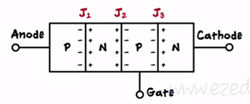
To turn ON the SCR the three junctions must be forward and biased. To forward biased J1 and J2 junction the anode voltage kept greater than the cathode voltage and for forward bias in J3 gate is given positive voltage with respect to cathode. (Vanode >Vcathode) and (Vgate > V cathode)
Consider two transistor analogies for SCR (Silicon controlled rectifier)
The transistor one is PNP transistor two is NPN. The collector or output transistor is connected to the base or input of the other. This explain interesting concept of latching of SCR.
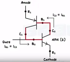
Latching means locking assume small external gate pulse is applied at base of transistor two. This makes B₂E₂ junction of transistor makes forward biased. C₂-B₂ junction makes the reversed biased. The transistor two switch ON the collector current IC2 flows through it which acts base current for transistor 1.
Now transistor one switches ON we get the collector of transistor one IC1 is connected to the base of transistor two. Hence IC1 acts an input for transistor two. In spite of removing external gate pulse applied at base2 SCR is remains locked or latched and continuously produces the output.
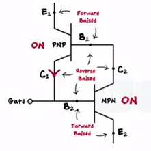
The only way to stop latching operation is to trigger the gate with negative pulse which will make B₂E₂ junction transistor to reverse biased so that it acts as open circuit and current flow stops.
Working of SCR ( Silicon controlled rectifier)
The SCR has three modes of operation they are
- Forward blocking mode
- Forward conduction mode
- Reverse blocking mode
Forward blocking mode
In forward blocking mode of the operation anode is given a positive voltage while cathode is given as negative voltage keeping the gate at zero potential is disconnected.
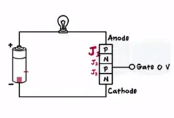
Junction J1 and J3 are forward biased while J2 is reversed biased due which small leakage current flows during this mode the SCR often very high resistance. The flow of current is set to be off state.
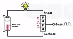
SCR can be brought from the blocking mode to the conduction mode in two ways.
To increase the anode voltage beyond break over voltage where break over voltage is the voltage at which the current flow starts in the SCR without the gate pulse. (Anode voltage > break over voltage) but this made damage to the SCR.
By applying positive potential at the gate and makes the junction J2 as forward biased and being all the three junctions forward biased the SCR conducts the current.
Once turned ON SCR goes into latching mode. There are two ways to make SCR conduction mode
First one is applying negative pulse at the gate which makes Junction J2 reverse biased and SCR comes out from conduction mode.
Once latched SCR remain ON till the current flowing through threshold level is called as holding current (Iscr > Iholding).
To bring SCR in the conduction mode current flowing through the SCR is reduced below holding current. This is the second way (Iscr < Iholding)
Reverse blocking mode
Negative voltage is applied to anode and positive voltage is applied to cathode. The junction J1 and J3 becomes reverse biased and junction J2 becomes forward biased and no current passes through it. This explain the SCR is the one way valve as current flow in only one direction anode to cathode.
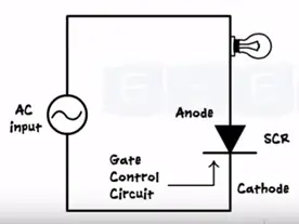
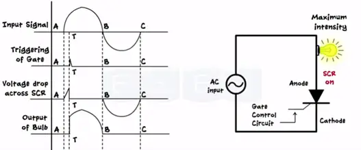
SCR as switch
We apply AC signal at the input SCR is one way device conducts only during positive half during the input signal.
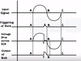
When the gate voltage is applied end of the positive half cycle the SCR turns ON and lamp glows with the minimum intensity only till the end of positive half as soon as negative half cycle starts lamp again goes OFF. SCR stops conducting.
In second case when we apply gate pulse at the peak point of positive half of the input. This enables SCR turn ON till the end of positive half and this case lamp gets glows at more intensity then the previous case.
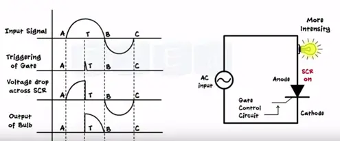
Let’s apply gate pulse at beginning of signal. The SCR turns ON early the lamp glows at maximum intensity from the point of application gate trigger till the end of positive half. Thus we get three different output for three different triggering position.

