Introduction In Types of Transformer:
Different types of Transformer are involving in transmitting and distributing power from the generation station to the consumer end. It is an energy conversion equipment that works under faradays electromagnetic principle. They are magnetically coupled and electrically isolated.
It consists of a winding, magnetic core, current transformer, protection devices, oil, etc. when you roam the roadside, you can see a small box connects with the wire and cables.
However, the types of transformer vary based on core construction, installation, voltage level, Instrument, Protection, and usage.
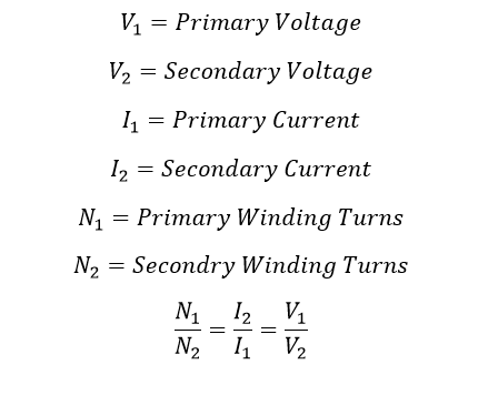
For easy understanding of the different type of transformer, we use some notations such as,
Different Types of Transformer:
- Power transformer
- Distribution transformer
- Control transformer
- Converter Transformer
- Lighting transformer
- Earthing Transformer
- Step-up transformer
- Step down transformer
- Isolation transformer
- Welding transformer
- Current transformer
- Voltage transformer
- Capacitive voltage transformer
- Loading Transformer
- Unit Auxiliary Transformer
- Summation current transformer
- Single-phase transformer and Three-phase transformer
- Interposing current transformer
- Indoor transformer & Outdoor transformer
- Air-Core Transformer
- Iron Core Transformer
- Ferrite Core Transformer
- Auto Transformer
- Rotary transformer
- Audio transformer
- RF Transformer
- Dry transformer
- Core Type Transformer
- Shell Type Transformer
- Berry Type Transformer
Step-up transformer:
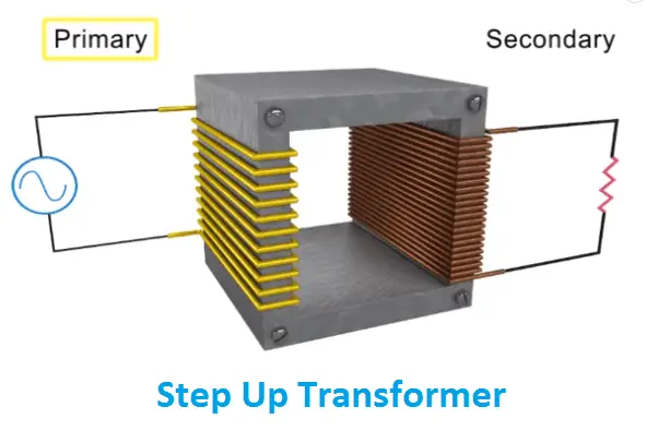
As the word state that, the voltage of the transformer will be stepped up. The primary voltage always less than the secondary voltage of the transformer.
Typically, V2>V1 and I1>I2, such as a type of transformer used in grid synchronization, measuring current flow in the high voltage line, etc.
Also see: Transformer Turns Ratio Calculator With Formula
Refer the fig 1.1 The number of turns in the primary winding is lesser than the number of turns in the secondary winding
Stepdown transformer:
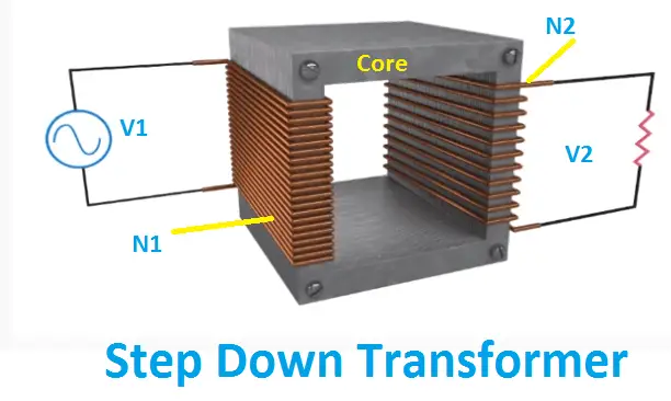
The opposite function of the step-up transformer is the stepdown transformer. The primary voltage of the transformer is very high and whose output will be reduced turns ratio of the input voltage.
Typically, V1 > V2 and I2 > I1
Also, by using a tap changer mechanism, you can change the voltage level for a certain percentage of the input voltage.
Power Transformer:
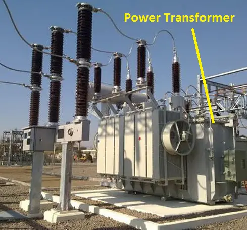
Generally, power is generated at the Generating station; Here power transformers are used to transfer power from the generating station to the distribution station. Mostly they are changing voltage level either step up or step down.
It matches the voltage level between the grid and the generator. Also, The direct voltage from the power transformer cannot be used. The voltage level of the power transformer will be around 6.6kV to 1200kV.
Power transformer manufactures along with the On load tap changer mechanism which is used to adjust the input voltage to the winding.
Example: India’s biggest power transformer is 630MVA located in Kerala.
Distribution transformer:
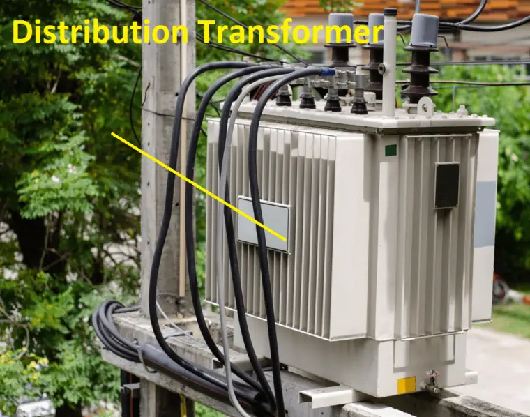
The output of the power transformer will be connected to the distribution transformer. They are mostly used in domestic applications such as human household supply, pump house, commercial building supply, etc.
The voltage of the distribution transformer will be from 1.1kV to 110V. They are mostly used as a step download transformer. Distribution transformer manufactures along with the offload changer mechanism.
Example: Roadside transformer 11kV/430V.
Isolation Types of Transformer:
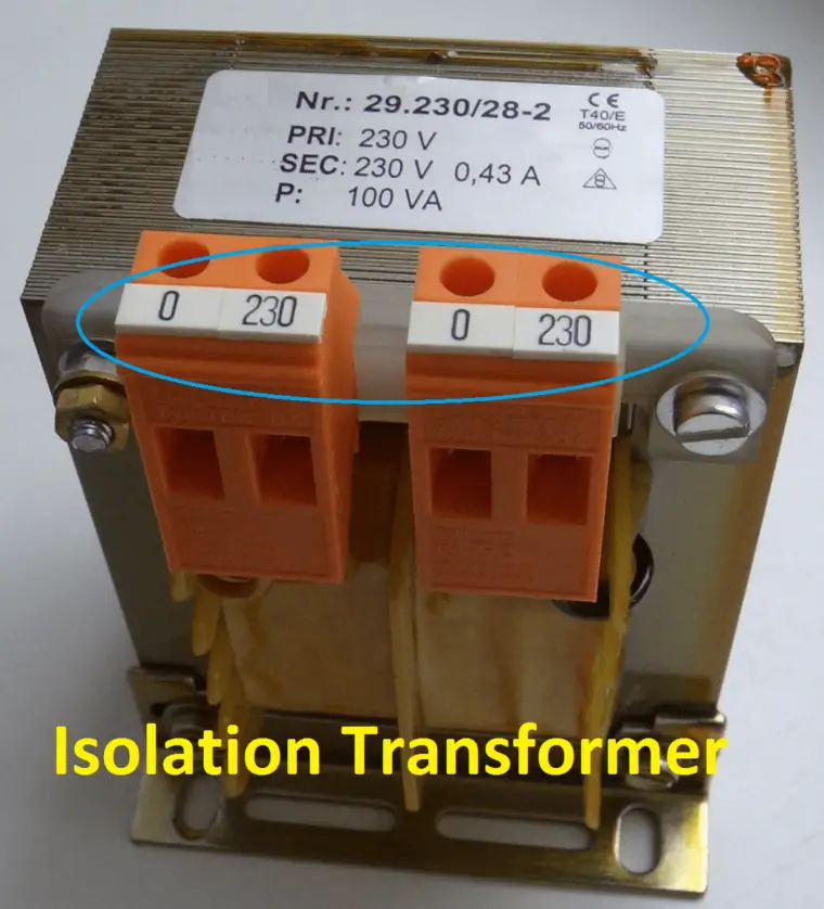
The primary number of turns is equal to a secondary number of turns. Typically, V1=V2 or 1:1, no voltage increment or decrement is going to happen on this transformer.
Such type of transformer is mostly used in instrument testing to protect from phase to earth fault circuit. The cost of the isolation transformer is higher than the same rating step up or step download transformer.
Control Transformer:
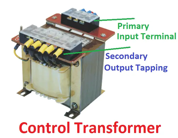
A control transformer is a small step down transformer is used in the electrical panels. They are having a voltage range of typically 440/230 or 690 to 230.
The main purpose of the control transformer is to protect the control circuit against the earth’s fault. It does not allow the fault to upstream breaker.
Converter Duty types of Transformer or zig-zag Transformer:
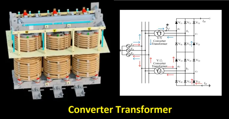
In many industries, the Converter duty transformer is mainly used for power electronic loads. It comes with a special setup called zigzag winding – star & delta.
The zigzag winding reduces the third harmonic which is generated by the electronics loads. Also, the zig-zag transformer has the advantage of both star (Neutral advantage) and delta (high voltage) connection.
Lighting Transformer:
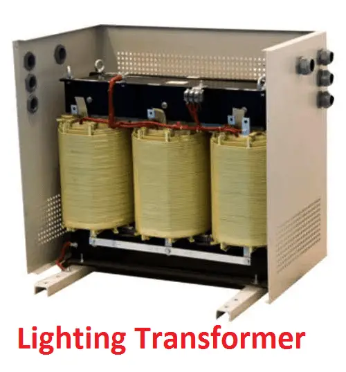
A small step down transformer whose secondary turns will the fractional multiplication of the primary windings. Such type of transformer is mainly focusing on energy saving on high lighting loads.
Typically, the voltage range will be 230/200 Volts. N1=fractional value*N2. Sometimes, lighting transformer act as an isolation transformer, since it is used to avoid tripping upstream breaker for small lighting failure.
Earthing Transformer:
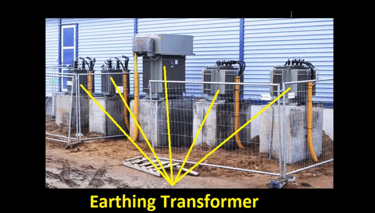
Earthing transformer is a single winding transformer that is used to ensure the neutral availability of the delta connected system. Delta connected system does not have the neutral, therefore the fault current will circuit through the windings.
To avoid such conditions earthing transformers are provided and that’s primary will be connected across the line and the neutral will be connected to the ground. During the fault, the fault current directly goes to the ground through an earthing transformer.
Welding transformer:

Have you ever seen welding? how the arc is being developed between the electrodes? The real truth behind is, that welding transformer is nothing but a small step down transformer whose secondary made of thick copper winding to carry high current. When touching of two terminals the high current starts to flow between the terminal which causes arc. The value of leakage reactance will be higher than the general transformer. It is also called a leakage transformer or stray field transformer.
Refer to Fig 1.10, The center core provides the isolation between the winding, by that we can get the desired output current from that transformer.
Also, welding transformer is classified into three types such as
- High Reactance model
- External Reactor model
- The integral reactor model
- The saturable reactor model
Current Transformer:
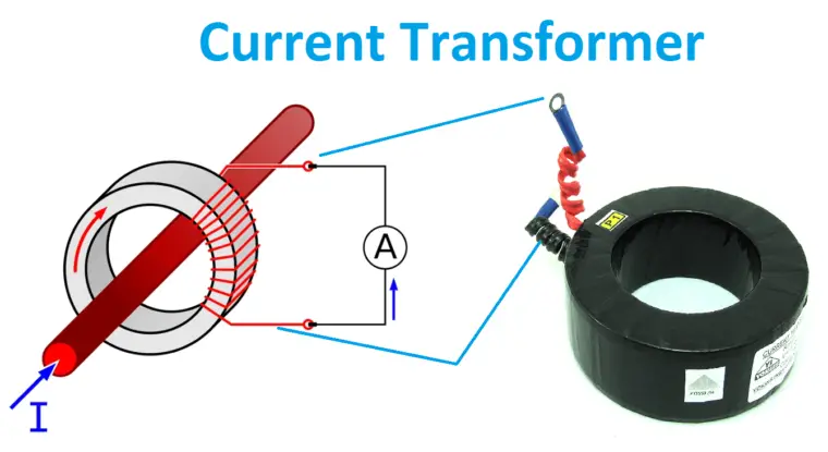
A current transformer is a voltage step-up transformer that is used are used to measure the line current. CT reduces high current level to a low current level, so that the ammeter, the relay can be connected directly without any external arrangements. CT consists of heavy primary winding with a lesser number of turns and thin secondary winding with a larger number of turns. The Primary of the current transformer is always connected in series with the line. Sometimes line itself acts as primary. Typically, the output of the secondary winding will be 1 A or 5 A and the same should be connected in the closed circuits.
Always secondary of the CT should be in closed conditions otherwise CT may get damaged. Also according to the core construction, CT is classified into four types such
- Wound Type
- Toroid Type
- Bar Type
- Summation Type
According to the usage,
- Metering CT: High accuracy transformer typically 2%. Here percentage indicates the metering core.
- Protection CT: Low accuracy, suitable to carry a high level of fault current (5p10). Here P indicate protection core
Summation current transformer:
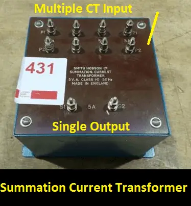
It a type of current transformer which is having more than one primary winding with the single secondary winding. It is used to reduce the usage of multiple numbers of meters. Also, it is a tailor-made item. i.e. now you have 4 number feeders by you have to monitor them by a single meter. In that condition, the output of the individual CT of all 4 feeders will be the input of the summation CT, hence you get single output. That single output measures the current of all feeders. Such type of transformer is called a summation transformer.
Interposing current transformer (ICT):
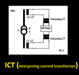
It is also a tailor-made CT. It is used for matching the CT ratio in the transformer’s differential and restricted earth fault protection. The output of the main CT will be connected input of the ICT current transformer. The out of ICT goes to the relay coil.
Potential Transformer (Voltage Transformer):
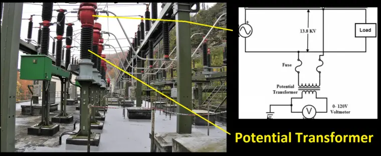
Hey, can you measure the output voltage of the power transformer directly? No, then what can you do? we have a solution for you, that is potential transformer. It a small step down transformer that will be connected in parallel with the mainline.
It converts the high non-measurable voltage into measurable low voltage. Typically, the output will be 63V or 110 volts. The insulation cost of the PT is high, and to reduce the cost PTs are always preferred to connect in star mode only. The one terminal of the PT will be connected to the ground always.
Capacitive Voltage transformer:
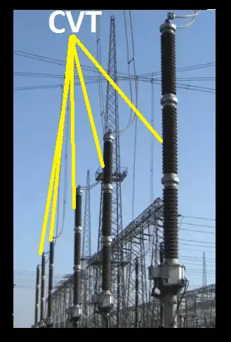
CVT or capacitive voltage transformer is a type of potential transformer which is used in Extra high voltage line such as above 110kV Line. The main purpose of this type of transformer is to reduce the cost since CVT has requires less insulation.
A pair of low capacitive reactance and high capacitive reactance will be connected in series with the primary and secondary winding.
Loading Transformer:
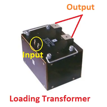
Such type of transformer is used to calibrate the instrument current transformer. The primary of the loading transformer has a high number of turns and secondary has fewer thick turns in other words loading transformer is a step-down transformer.
The calibration will be taken by connecting the secondary of the loading transformer and primary of the calibration CT by a series connection. The output of the instrument CT and input of the loading transformer will be compared and based on that result, the error value will be generated.
Unit Auxiliary Transformer (UAT):
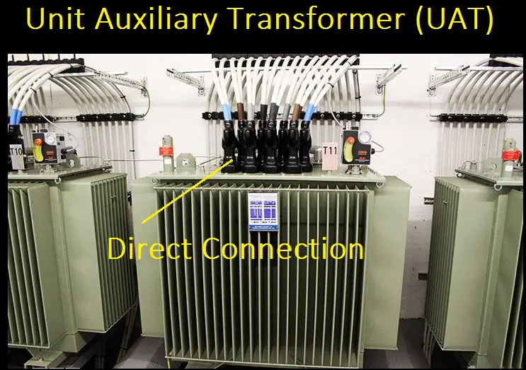
UAT type of transformers is nothing but a simple transformer that is connected along with the generator directly. The main purpose of UAT is to avoid tripping (due to inrush current) of small generators while charging a higher rating transformer. The transformer’s voltage gets build along with the generator voltage.
Single-phase and three-phase transformer:
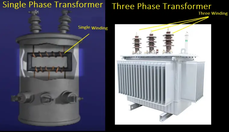
Single-phase transformer: The transformer is designed to supply only one phase; such type of transformer is called a single-phase transformer. It has a single secondary winding with single or multiple primary winding. Also, one terminal of the single-phase transformer considers as neutral.
Three-phase transformer: A small step up/step down transformer with three input and output winding transformer is called a three-phase transformer. This type of transformer is used to supply the desired voltage to the three-phase load. Example: Power and distribution transformer.
Indoor and Outdoor Type transformer:
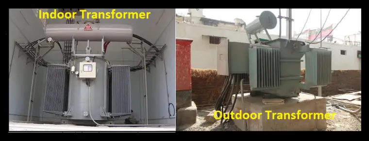
Indoor Transformer: The name suggests indoor = in+door, the type of transformer strictly used inside of the room such a transformer is called an indoor transformer. They do not design with the weatherproof. They are covered by the concrete roof sheet. The life span of the indoor type of transformer is higher than the outdoor transformer. The indoor type transformer has less operating voltage range up to 22kV.
Outdoor transformer: The type of transformer best suitable for open area application. The transformer should have a minimum of IP 45 enclosure. Almost 95% of the transformers are being manufactured to fit the outdoor application. It does not require any roof sheet and they are suitable for high voltage applications as well as low voltage applications.
Air core type transformer:
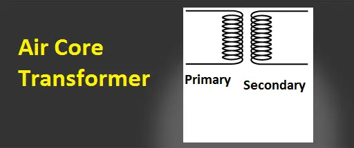
The transformer does not have a core between primary and secondary windings. The flux linkages between these two coils will happen through the air, that why this type of transformer is called an air-core transformer. Sometime toroidal types of air-core transformer, the primary and secondary wound on the top of the hard plastic or nonmetallic substances. It is mainly used to reduce the noise in high-frequency applications.
Iron Core Type Transformer:
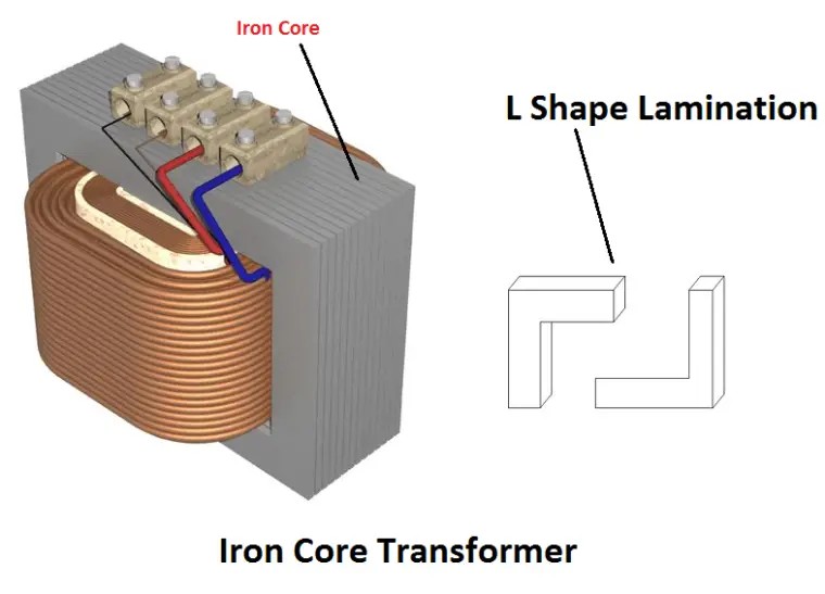
A core is a flux carrying part which is made up of iron material. Such type of transformer is called an Iron core transformer. You know iron is a conductor while carrying magnetic flux, it produces current flow across it. Hence a small amount of silica will be added with the pure iron to reduce the losses by increasing resistivity of the material.
Example: Power and distribution transformer.
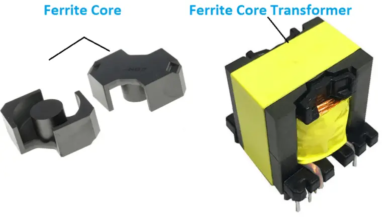
Ferrite core Type transformer:
The transformer core made up of non-conductive, ceramic, ferromagnetic compounds, and the resistivity of the ferrite core transformer is high, hence the eddy current losses are low. Also, the transformer is made of adjustable inductance value. Ferrite core types of transformers are used in high-frequency converters, radiofrequency, SMPS, AM radio receivers, etc.
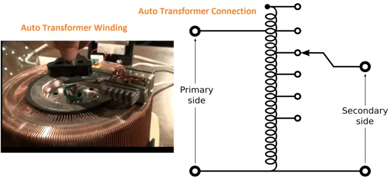
Autotransformer:
A unique type of transformer, which has only one winding. In that single winding, some portions work as the primary and secondary winding. The winding of the transformer comes with a minimum of three steps to adjust the output voltage value.
The main advantage is lower leakage reactance, lightweight, cheaper, etc. the main disadvantage is the single winding act as primary and secondary of the transformer, hence there is no electrical isolation between the windings. So, they cannot be used in high voltage/high current applications.
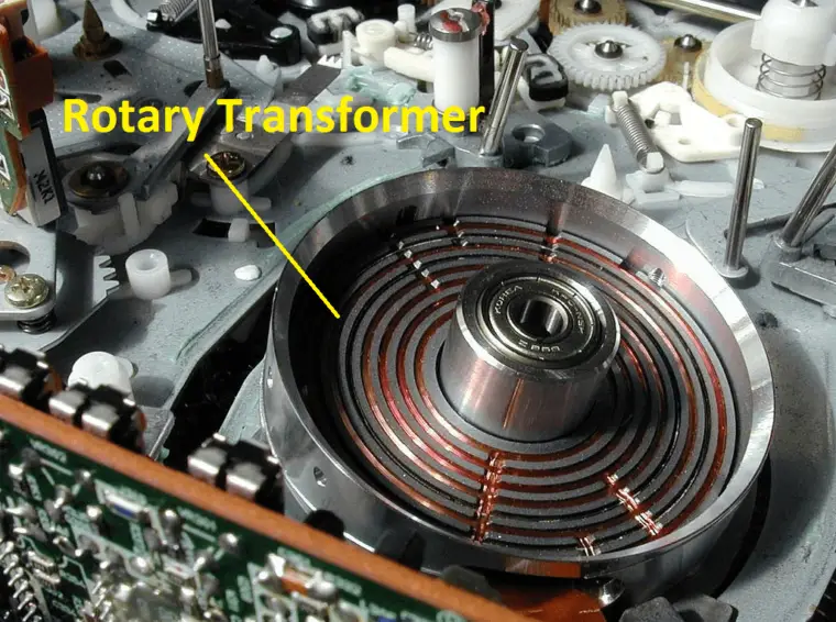
Rotary Transformer:
Have you seen a slip ring, that is used to transfer electricity from a rotating part? But they have many disadvantages such as loss of signal, wear, and tear, speed limitation, etc. To avoid the disadvantages, the rotary transformer is used. The primary of the transformer is mounted on the shaft of the rotating part and the second part will be connected to the external circuits. Here, there is no electrical contact between the rotating part and external circuits.
Rotary transformers are mainly used in torque sensors, videocassette recorders, DVD players, etc. also remember that rotary transformer works only AC signal No in DC.
Audio & Radio Frequency transformer:
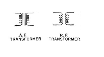
Audio Transformer:
As the name indicates, an audio transformer is used to match the impedance of the amplifier circuits. It has an operating frequency of 20Hz to 20,000Hz. Also, it removes the DC signal present in the input signal and provides the electrical isolation between the input and output of the circuit.
Radio Frequency transformer:
RF transformers are used in the RF, VHF and UHF circuit to filter out the electromagnetic interference present in the input signal and impedance matching circuits.
Core type Transformer:
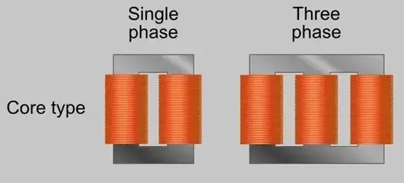
The winding of the primary and secondary wound on the two limbs of the rectangular frame which is formed by connecting two L shaped lamination. Such an arrangement creates large leakage reactance. To reduce the leakage reactance half of the primary winding and secondary winding will be wound closely on two limbs. The LV winding wound on the core first and then it is surrounded by the HV winding. That’s why this type of transformer is called the core type transformer.
The core type of transformer is used in low voltage applications.
Shell Type transformer:
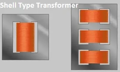
The core surrounds the winding; it means the winding is being done inside the core as shown in the figure. The HV winding wound alternatively followed by the LV winding. In other words, sand witched winding, I mean first HV winding and next LV winding like that. The leakage reactance of the shell type of transformer is very less.
Shell type transformer is suitable for High voltage applications.
Berry Type Transformer:
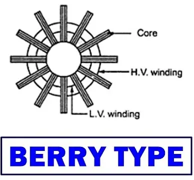
It is a special type of shell-type transformer which core is constructed like a spokes wheel. The coil wound in a cylindrical shape.

