Ferranti Effect:
In long Transmission Line or cable, the receiving end voltage is greater than the sending end voltage during light load or no-load operation. Under No-load or light load condition, the capacitance associated with the line generate more reactive power than the reactive power which is absorbed, hence Vr > Vs. This effect is called is known as Ferranti effect.
In short transmission Line (the line has the distance of only below 50kms), the shunt capacitance is neglected. So this phenomenon occurs in medium (50kms to 240kms )and long transmission lines (above 240kms).
Why Ferranti occurs in Long Transmission line:
A long transmission lines more than 240kms are consisting of high amount of capacitance and inductance distributed across the entire length of the line. Ferranti Effect occurs when current drawn by the distributed capacitance of the line itself is greater than the current associated with the load at the receiving end of the line (during light or no load). This capacitor charging current leads to a voltage drop across the line inductor of the transmission system which is in phase with the sending end voltages. This voltage drop keeps on increasing additionaly as we move towards the load end of the line and subsequently, the receiving end voltage tends to get larger than applied voltage leading to the phenomena called Ferranti effect in power system
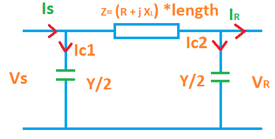
Represent Long Transmission line by equivalent π-model.
Consider the following
VR = Receiving end Voltage
VS = Sending End Voltage
IL = Line current
IS = Current at Sending End
IR = Receiving end current
IC1 = Line Capacitive current at sending end
IC2 = Line Capacitive current at receiving end
Z = Line Impedance
R = Line resistance
L = inductance of the transmission line
C= capacitance of the line.
Y = conductance of the line
l= length of the conductor
XL = Inductive Reactance of the conductor
[wp_ad_camp_2]
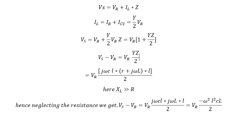
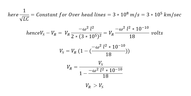
Here you can see that the decreased dominator value increases the total value..
How to reduce Ferranti effect:
- Ferranti effect can be reduced by installing shunt compensation devices at receiving end. The compensation device is a shunt reactor which is connected in parallel with the transmission line. It reduces the voltage level by absorbing the reactive power.
- Running the transmission line with higher load. I.e if you have two line both carries 5 % load in each side means, we can switch of the one transmission line and the remaining load can be diverted in to another one.
Also see:
- Wave Trap Working Function & Purpose of Line Trap
- What is Skin Effect | Reduce Skin Effect in Transmission Lines
- What is Proximity Effect | Reduce Proximity Effect
- What is The Purpose Of Stockbridge Damper In Transmission Line
- CVT in Electrical Capacitive Voltage Transformer CVT
- Difference Between RYB and UVW
- Difference between Surge Arrester, Lightning Arrester and Lightning Rod
- Directional Over Current & Non Directional Over Current Protection Working Principle
- Distance Protection Working Principle & Fault Location Detection
- What is Creepage and Clearance Distance of Insulator?
- Why Earthing Transformer are used
- Why High Voltage is Preferred to Transmit the Power
- Why in India 11kV, 22kV, 33kV, 66kV, 132kV…
- Why India has 50 Hz Power System and US has 60 Hz 110 Volts Power System
- Why Does Bird Not Get Shock on Transmission lines?

![Why Synchronous Motor is Not Self Starting [Simple Explanation]](https://electrical4u.net/wp-content/uploads/2020/06/Synchronous-motor-is-not-self-starting-218x150.png)
