Rotor Earth fault Relay 64R working Function:
Rotor earth fault relay 64R which is used to protect the generator or alternator rotor against earth fault (the short circuit between rotor’s winding to ground). It senses the alternator’s rotor earth leakage current. The ANSI code for rotor earth fault relay is 64R. let see the rotor earth fault relay working function.
There are two kind or rotor earth fault relays are normally implemented. One is current based and another one is resistance based. In this, we are going to see current based rotor earth fault relay.
Rotor Earth fault relay Diagram:
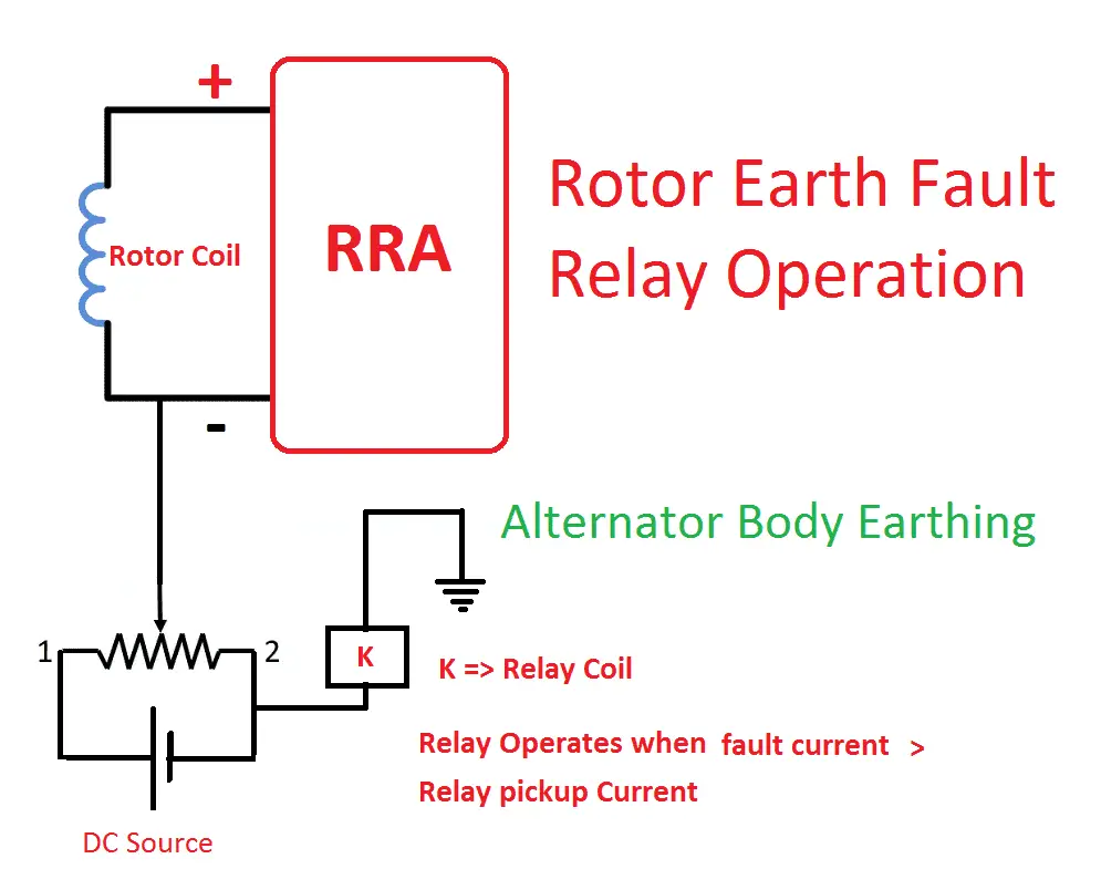
Rotor Earth fault Relay diagram explanation:
Consider the alternator rotor coil terminal L1 and L2 which is connected with the RRA (Rotating Rectifier Assembly). The external DC supply +ve will be given to the rotor winding L1 or L2. But we should not connect it both terminal. The negative terminal of the DC source connected with alternator or generator body. The rheostat will be connected in series with the +ve of the DC source. The rheostat is used to vary the injected voltage range. The over current relay element will be connected in series with the rheostat. The overcurrent element is used to trip the associated circuit breaker when the fault occurs in the rotor.
Rotor Earth fault Relay operation:
The DC voltage will be injected to the generator rotor coil. During Normal condition the current flow through the rotor coil to ground will be zero or the resistance between the rotor coil to ground will be infinity or maximum. During fault condition, the resistance between the rotor coil to earth will become zero or very less. Then there is a current flow through rotor to earth (alternator body). The alternator body is directly connected with negative terminal of the source. Then the leakage current flow through the DC source and if the leakage current is greater than the pickup current of the over current element means the relay will get trip.
[wp_ad_camp_1]
The rotor earth fault relay contains two stage of tripping, first stage and second stage. The first stage connects with alarm circuit and second stage connect with trip circuit.





![What is Arc Chute? Types, Working Principle [Video Included] arc chute working priciple](https://electrical4u.net/wp-content/uploads/2020/06/arc-chute-218x150.png)
