Calculate stabilizing resistor for Differential Protection:
In a three-phase alternating power system, the bus bar differential protection needs to be stabilized, because the differential relay should not trip if the fault outside of the protective Zone.
For example, let us consider a through fault occurs outside of the protected zone means, the same heavy fault current will be read by our differential protection’s current, and due to heavy primary current, the CT may get saturated.
Also see: Reason for Current Transformer Saturation
Due to this, there is an unbalance current will flow in the relay operating coil.
Hence, the relay trips the associated circuit breaker. The fact is, the relay should not trip the circuit breaker in such a condition which means the relay is designed not to trip the CB when the fault is outside of the protective zone.
In order to avoid or to increase differential relay stability, we need to add a stabilizing resistor while designing a high impedance differential relay.
What is a stabilizing resistor?
As the name suggests, a resistor is used to increase the stability of the circuit, and a stabilizing resistor is a set of a resistor is connected in series with the current transformer’s secondary terminal.
How the stabilizing resistor Increases relay stability?
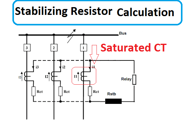
The three identical current transformers CT1, CT2, and CT3 are connected as shown in the Fig 1.1.
Consider 3 CT’s internal resistance such as R1, R2, and R3. Being high impedance differential CT configuration the internal resistance of all CTs are equal R1 = R2 = R3 =RCT
The current flow through the three Current transformers such as I1, I2, and I3. Under Normal condition I1 + I2 + I3 =0. (No fault) , Hence the operating coil does not operate the trip circuit.
During the fault condition (fault inside of the protective zone) the I1 + I2 + I3 is not equal to 0. Hence the relay operates the trip mechanism. This is done by a normal differential relay.
But if the fault is outside of the protective zone i.e through fault, consider the worst-case scenario, out of three CT, one of the current transformer core got saturated.
I our case, let us consider CT3 got saturated. Then the fault current flows through the CT3. Then there is a voltage drop VCT3 devolved across the CT3 is
If the relay configured at the panel board side means there, pilot wire (looping wire) resistance will be added. Hence,
Here 2 * Rwire means CT has two terminal S1 and S2 hence we need two-wire to bring the current transformer’s output to the panel board.
This voltage operates the operating overcurrent element (operating coil)….To withstand this voltage we have to add a resistor in series with the overcurrent element (operating coil).
Calculate the stabilizing resistor:
In this, we are going to use the potential divider principle. We are going to divide or balance the voltage across the operating coil by adding the resistor in series.
Let’s us assume the current setting in the over-current element is Is
Then
Here the resistance of the operating coil is very low. Typically
Hence,
If the relay configured at CT terminal side means..
Thus during through fault, for the worst condition of CT saturation, the current through the Relay coil will not be enough to cross the setting value of Is and thus the relay does not operate.
Example of ABB Stabilizing Resistor:
Let us consider an example of ABB, The protective relays type SPAE 010 and SPAE
011 forms are the high impedance type differential protection. Both are used as differential and earth-fault protection for transformers, generators, and motors.
Here SPAE 010 requires 80 to 265 VAC but SPAE requires 18 to 80 VDC.
Both are stable for all types of faults outside the zone of protection. The stabilization is ensured by a series resistor in the differential circuit.
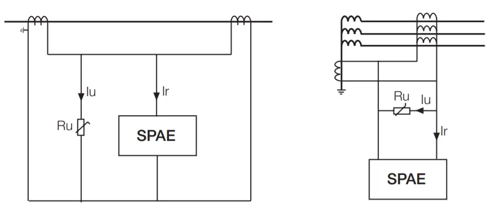
Look at the image, In SPAE 010 and SPAE 011, the connected stabilizing resistor Ru is included in the relay and is in series with the measuring transformer. Now you can understand the name of high impedance. The system impedance is increased by connecting a resistor.
Stabilizing Resistor working in SPAE Relay:
The relay stability of this protection works based on the impedance of a current
transformer rapidly decreases as the same saturates. During the time, the reactance of the CT is zero, here the total impedance is equal to the winding resistance.
Also see: Transformer Primary and Secondary Current Calculator & kVA to I
It means that the resistor in the differential current circuit these secondary current fed by a non-saturated a current transformer is forced to flow through the secondary circuit of a saturated current transformer.
The operating level of the high impedance relay is to be set to a level not permitting a relay
the operation for any currents in the differential current circuit, caused by any fault currents arisen by faults outside the zone of protection of the high impedance protection.
When a fault arises within the zone of protection, both current transformers strive to feed
current through the differential current circuit and the protection will operate.
Key Concept of Stabilizing Resistor:
Under Fault condition (outside of the protective zone), the relay should not get statute. Since under CT saturation, the impedance of the CT starts decreasing. Due to this saturation of one CT, the unbalance current will flow in the relay coil.
In order to overcome this, we are adding an external resistance in series with the CT secondary to increase the impedance of the CT and stops the addition of a high current through the circuit.
In such a way, relay stability will be increased.
Ref: https://library.e.abb.com/public/7320a145aa0a411bc2256bf0004ca0f6/FM_SPAE01_EN_B.pdf





![What is Arc Chute? Types, Working Principle [Video Included] arc chute working priciple](https://electrical4u.net/wp-content/uploads/2020/06/arc-chute-218x150.png)
