Motor Protection Relay MPR Relay Working Principle:
Motor Protection relays are used to protect the higher HP high voltage induction motor. When we increase the motor output power according to that we have to increase the input voltage to the motor. Why we have to increase the motor input voltage? By increasing the voltage, we can reduce the full load current of the motor. So that, we can significantly reduce the eddy current and hysteresis losses of the motor. To protect, high voltage motor we uses motor protection relay. It is also called as MPR. These relays are mostly used for most of the application such as cutter, grinder, roller mill, mixers, chopper etc.
Let’s see the fault arise in an induction Motor:
- Overcurrent fault
- Single phasing
- Earth fault
- Bearing failure fault
- High Winding temperature
- Short circuit
MPR Motor Protection Relay Protection:
The motor protection relay consists of the following protection.
- Motor Over Current Protection
- Locker rotor protection
- Locked Rotor protection
- Current unbalance protection
- Earth Fault protection
- Short circuit Protection
- Number of Hot Start
Over load Fault:
Overload is not a fault, but it is also considered as a fault. Over load is nothing but a motor operates more than its full load current. Normally motors are designed to operate a particular amount of current typically 110 to 125% of its full load current. But due to some mechanical conditions i.e pump needs extra high input therefore motor delivers extra output. This output will be drawn from input supply. But delivering the extra output causes increasing the burden of the motor. This is called overload fault. In this fault, all three phase of the motor takes equal current.
Overload Protection:
In this protection limit the current flow to the motor. Generally, the setting will be available in % percentage of the full load current. if the current flow increases than the preset value, then it will trip the circuit breaker.
[wp_ad_camp_2]
Note:
- For Small size induction motor, thermal overload relay does the exact duty of the overload protection.
Single phasing:
Single phasing is nothing but a running a motor with two phase instead of three phase. This is a very dangerous fault. This is very important protection for induction motor and this must be avoided. Upon failure of one phase of the motor which means the current flow through the same phase is equal to zero, therefore the motor tries to manage the load with the remaining two phases. Therefore, the load current on the remaining phase increases into 1.5 times. Single phasing occurs due to motor terminal leads got open, one of the incoming power supply failure, incoming fuse failure etc. This fault causes increasing the winding temperature of the motor. Finally, motor get failed.
Coming to the protection, the motor protection relay sense the input supply and the current flow through to the motor. The voltage and current reference will be taken from the potential transformer and current transformer of the motor.
Note: For small size motor we use separe single phase preventer to protect the motor from single phasing. Learn about single phase preventer here.
Earth fault:
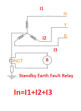
Earth fault means the one or two or three phase of the motor get contact with the earth point. Therefore, the entire current flow in to the earth. This is fault must be avoided. It cause increasing the neutral voltage, loss of resource. High fault current may damage the other electrical equipment etc. earth fault occurs due to the motor terminal outgoing cable insulation failure, winding insulation failure, heavy inrush current etc.
Also see:
- How to Repair Electrical Wire Insulation Failure
- Types of insulation class motor winding Technology
- ELCB Earth Leakage Circuit Breaker | Ground Fault Protection
Earth fault protection:
In this, the fault protection consists of two setting. One is high set (>>) earth fault and another one is low set (>) earth fault. In high set earth fault is called instantaneous earth fault protection. It protects the motor against instantaneous earth fault and which trip the circuit breaker without time delay. In low set the relay trip the motor with IDMT curve based. Typically, mpr relay setting for a 2.0MVA, 11kV, 103 Amps Induction motor. Ia is the full load current of the motor.
Motor winding temperature high:
This is very rare fault, because of all the motors are designed to operate at continuously typically S1 & S2 duty. This is depending upon the insulation class and the number of starting and number of operating hours. But even though, the motor winding temperature get increase due to falling of additional loads on the motor, insufficient cooling, some other faults such as inter turn short circuit and earth fault nearer to the end of the star connection etc.
Motor Winding Temperature Protection:
The motor temperature will be measured by RTD (resistance temperature transducer) which will be placed inside of the motor winding. The RTD is working under the principle of the resistance of the RTD get increase as the increasing in temperature. The MPR relay sense the temperature of the motor. The winding temperature protection consist of two stage operation. The first stage consists of alarm stage, which activate the alarm circuit and second stage trips the circuit breaker.
Note: In this, six number of RTD are used and each phase consist of two RTD.
Bearing Failure:
Almost 95% of the motor failures occurs due to the bearing failure only. Bearing is used to rotate the motor’s rotor. In any motor contains latest minimum two number of bearings. The failure of bearing causes damages the rotor slots (rotor slots starts rub on the stator), damages the winding insulation, increases the motor’s stator and rotor temperature etc. 65% of bearing failure occurs due to misalignment between the motor shaft and mechanical loads. Another 35% of failure occurs due to the insufficient bearing cooling (lack of oil or grease or water).
Bearing failure protection:
In this protection, the RTD placed inside of the bearing housing or encloser. It is also same like winding temperature protection, two stage operation.
You May Like to Know:
- IP Enclosure Ratings & Standards Electrical Equipments
- Types of Encloser employed in induction motor
Locked Rotor:
In that word locked rotor, you can know about it “the rotor locked” which means the induction motor rotor got struck or jam. This fault occurs due to mechanical equipment failure, motor bearing failures, foreign material struck inside of the stator and rotor air gap etc. This is very dangerous fault and this is very rare case but the corrective action to be done. During this fault the induction motor takes 3 to 5 times of its full load current. this high current damages the winding as well as insulation.
The Locked rotor protection setting for the same motor.
Hot Start:
Number hot start limits the number of immediate starting of the high voltage induction motor. Purpose of this protection is to protect the motor from insulation failure. Because of each time while starting takes high inrush current typically 5 to 7 times of the full load current and which increases the winding temperature of the motor. The temperature rises may damage the insulation as well as winding. In factor the hot start setting will be 3 times. After starting of 3 times, the locking timer gets switched on. Then the motor protection relay does not allow you to start the induction motor until the timer reach the preset timing.
The Hot start setting for the same motor is..
[wp_ad_camp_2]
If you start the same motor 5 times within one hour the next sixth start the timer does not allow you to start. You can start the same motor after 2 hours from the fifth start.
Current Unbalance fault:
The unbalance current means variation in the flow of three phase current. This fault mostly occurs due to the quality of the copper (high resistance copper) used while manufacturing or while rewinding of the motor. Many motor re-winder to increase their profit on motor rewinding business, they use less quality copper for the high voltage motor, variation in the incoming voltage and inter turn short, flow of harmonic current etc. This cause current unbalance.
Current Unbalance protection:
This protection trips the circuit breaker when the unbalance current reaches than preset value. The unbalance protection does not trip the circuit breaker immediately. Unbalance current setting for the same motor…
Short Circuit Protection:
Short circuit means the contact occurs between the phase which cause immediate flow of high current. It consists of two stage one is instantaneous short circuit protection and another one is short circuit Ist protection with Inverse time delay. The relay setting of the same motor is
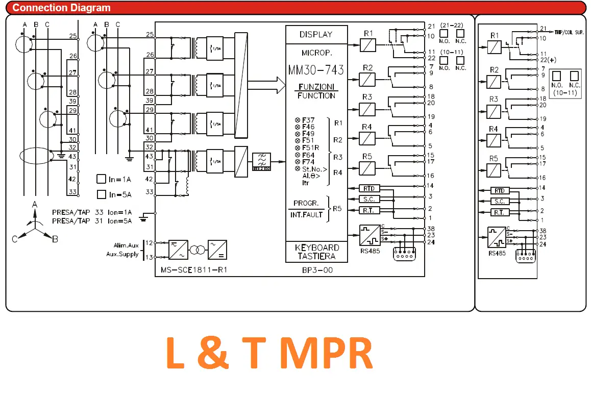
The Circuit diagram of l&T make MPR for higher HP motor.
Also See:
- What is skewing of an induction motor?
- What is Slip of the Induction motor
- What is Slip ring induction motor Practical explanation and Pictured
- Why induction motor Takes high starting current
- Why Inductors Use In Filtering Circuit and VFDs
- Why Slip ring Induction motor is preferred for High starting Torque application
- Slip ring induction motor SRIM vs squirrel cage induction motor SCIM
- Directional Over Current & Non Directional Over Current Protection Working Principle
- Distance Protection Working Principle & Fault Location Detection
- Merz Price Differential Protection for Generators


