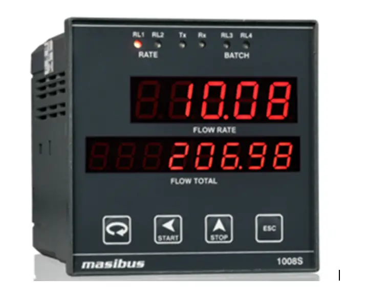
First understand the working principle of digital flow indicator.
The 4-20 mA output signal of the electronic transmitter is used as a input signal in all type of electronic flow indicator come totalizer. In the first stage it is converted into voltage signal.
This signal is now divided into two different electronic circuit.in the first circuit this signal is given to analog to digital converter and output of ADC is connected to the seven segment display for the flow rate indication.
Similarly in another electronic circuit the voltage is converted into frequency signal(i.e. is pulse) with the help of voltage – frequency converter and this signal is connected to transmitter which is acting as ‘ON-OFF’ switch and operate relay accordingly.
In this way six digit electro mechanical counter registers the data by counter increment system and show the total readings for hour/day/week of the flow.
Equipments required for calibration.
- Flow indicator come totalizer
- Universal calibrator
Calibration Procedure:
Step 1: Press the mA parameter switch
Step 2: Press the 20 mA range switch
Step 3: Connect the short link between the mA o/p & -ve sense terminal
Step 4: Connect the +ve sense terminal to the input terminal of the FIQ
Step 5: Connect the output terminal to negative and input terminal to the FIQ
Step 6: Switch ON the unical
Step 7: Press the output switch adjust on unical 20 mA display with halp of span coarse and fine potentiometer knob
Step 8: Switch ON the FIQ and give the 4mA input to FIQ observe the display it must br 0000 if not adjust with zero knob
Step 9: Now give the 20 mA input to FIQ and observe the display reading it should show the predicted range reading if not adjust with the help of span knob
Step 10: Repeat the procedure step 8 & step 9 till the stastificatory readings observed on display
Step 11: Now give the different mA input to FIQ and observe the reading
Step 12: Again give the 20 mA input to FIQ and observe the counter value reading that should be equal to predicted range value.If not adjust with counter adjustment knob till sastificatory count reading


 Conversion Calculator DC, 1 Phase, 3 Phase")


