What is Cogging of Induction Motor Definition and Explanation:
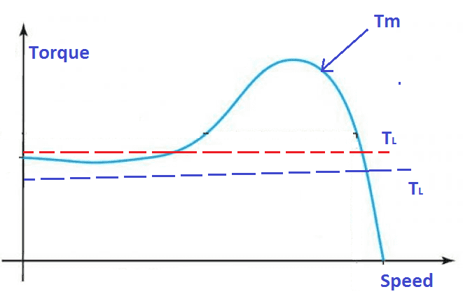
Consider a Speed Torque characteristics of the induction motor. Let us consider Tm is motor torque or driving torque and TL is load torque. In our first case, the see the blue color dotted line where the driving torque is always higher than the load torque which has stable operation until the drive torque fall. Next take red color line in that, the drive Torque Tm is lesser than the Load Torque, where the motor does not rotate even when full voltage is applied to the stator winding. This is called Cogging of induction motor.
Let’s see the detailed explanation,
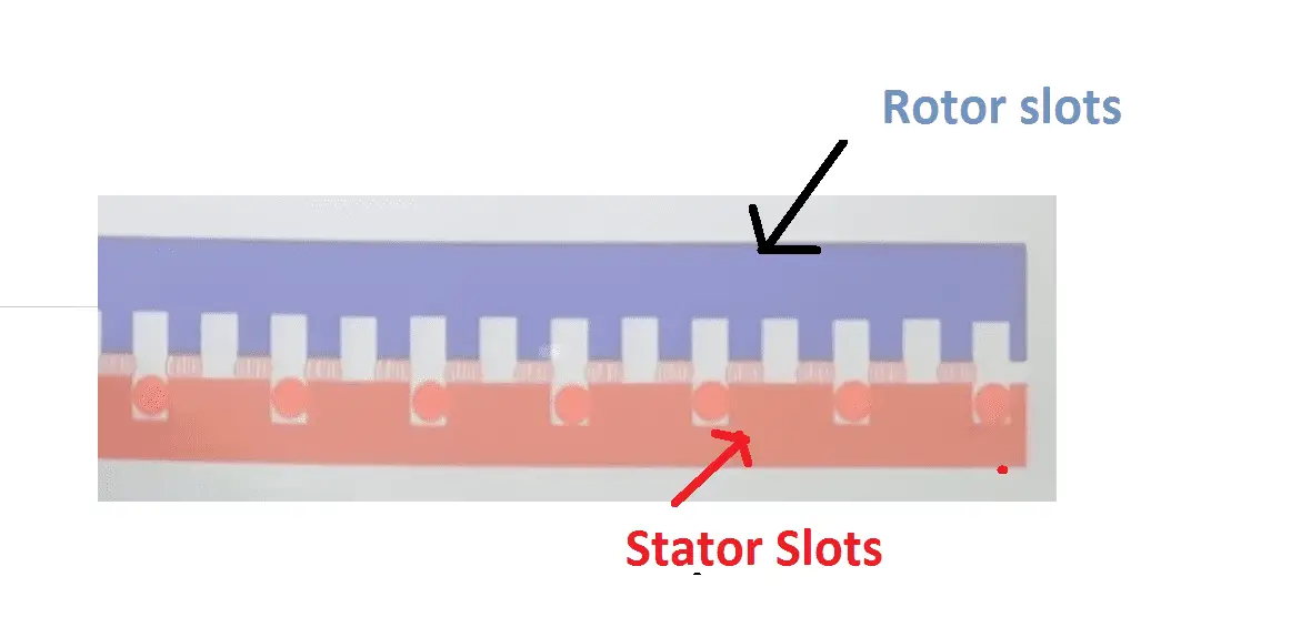
This phenomenon generally occurs when the rotor slots is equal to stator slots or stator slots is equal to integer multiplication stator slots. i.e consider If the number of S1 (starter slots) equal to rotor Slot, or integer multiples of by, see the picture.
[wp_ad_camp_2]
Generally motor consist of stator conductor and rotor conductor. They are placed inside of the slots. When the stator slots are equal to rotor slots, both are faces each other, hence a strong magnetic alignment force created between the rotor and stator slots. This force opposite the motor drive force. Hence the motor failure to rotate. This is called Cogging of Induction motor
How to avoid cogging of induction Motor:?
- Generally cogging of induction motor can be avoided by rotor skewing method. Rotor skewing is nothing but aligning the rotor slots with angle. This angle difference reduces the slots alignment force.
- Manufacturing a motor with fractional slots between the stator and rotor. i.e stator slots is 36 means we have to make motor’s rotor with 34 slots. Hence ratio will be 36/34= 1.05.
Video Explanation of Cogging of Induction Motor:

Subscribe This Youtube Chennel for More Videos:
[wp_ad_camp_2]
http://www.youtube.com/c/PiSquareAcademy?sub_confirmation=1






Thank you very much sir. Your explanation is always very fine