What is alternator:
The alternator is the machine which converts mechanical energy into electrical energy. It is same like the generator. Alternator works under Fleming right-hand rule…” momentary conductor is kept in the magnetic field which induces emf. This rule is used to determine the direction of current in a generator’s windings. First, all must know what is the difference between alternator and generator.
[wp_ad_camp_1]
Alternator:
Here the main field winding considers as a rotation part and the armature will be standing. The larger rotor coil considers as main field winding, which is driven by the prime mover. The main rotating field winding is responsible for generating main flux. It is maintenance free, does not require larger size carbon brushes to get output from the armature winding.
Generator:
Here the main field winding considers as stationary part and the armature is the rotation part. The output from the generator is taken through carbon brushes. It needs larger size carbon brushes and periodic maintenance.
Coming to the alternator excitation system which is excited by two types of excitation system.
- Brushless excitation system
- Brush excitation system
Brush excitation system:
This is an old technique to excite an alternator. Such excitation system is used in a small alternator. That means low KVA output alternator. The direct DC supply is given to the alternator main field coil through carbon brushes. The field voltage is control by AVR automatic voltage regulator or rheostatic control.
Brushless excitation system:
Now a day almost 99% of the alternator is designed by this kind of excitation system. It considers of a larger part such as excitation generators, and RRA (rotating rectifier assembly). With the increase in rating of an alternator, the supply voltage and the output current must be high. This is system has more advantage than brush excitation system. Even I have seen almost 12 alternators, in that out of 12, 11 alternators were brushless excitation system and only one very old alternator had brush excitation. Even the owner of the alternator has planned to replace the same. But this kind of excitation Costlier; due to its construction. But maintenance free; It has some disadvantage if any diode failure we have to stop the entire machine to replace the faulty diode part.
PMG: Permanent magnet generator:
This is another part of the alternator, which used to produce excitation voltage to the main field winding, Basically, the PMG has a higher number of poles, to reduce the transformer size in the AVR panel.
FAQ: Which PMG poles are Higher than main poles
There are three reasons
- When the increase in PMG poles, the corresponding output frequency also increases due to this the transformer Size on the AVR side also get reduced. Because of Transformer size is indirectly proportional to the frequency. Finally, we will get easy and reduced transformer construction,
- As of everyone Knows Alternator generator voltage E is directly proportional to flux and frequency… So that by reducing the speed of the alternator reduces the output frequency, this speed reduction should not affect the PMG output voltage.
- Easy Replacement: Upon Failure of a magnet or Low strengthen magnet, it is easy to replace the particular pole. The Cost is less for the small size of the magnet as compared to higher size magnet with less number of the pole.
AVR: AVR is called as automatic Voltage regulator:
This is an electronic circuit which converts PMG output AC Voltage to controlled input DC voltage to the Ac excitation generator. AVR is used to regulate the output voltage of the alternator. It is regulating the alternator output voltage by controlling input to the ac exciter. This is main control section of an alternator. Particular during Synchronous condition helps to maintain the output power factor. Also, this control section only decides the alternator either to be run on active power generator or reactive power generator.
AVR Backup Section:
The AVR contains excitation Transformer, which uses at that time of failure or malfunctioning in the AVR circuits. But practically this is not advisable to run an alternator with excitation transformer. It’s very dangerous to the turbine. This section only monitors the RRA diode healthiness.
Ac Excitation generator:
From the heading itself you can come to know its generator, already we have discussed the difference between the generator and alternator. In an excitation generator, the main fields winding are in standstill position and the armature is the rotation condition. Her the output voltage of the excitation generator goes to the RRA assembly, which converts AC input voltage to DC Output voltage. The AVR input voltage is given to the excitation generator, Typically the value between 5 Amps to 50 amps depending upon the alternator capacity. For 24 MW alternator, the AVR output voltage is 65 V VDC, 6.95 Amps. But in the excitation transformer produces around 240 VAC, 280 Amps the same Input voltage with full load condition. The phase requirement of the ac excitation generator is purely depending upon the alternator main field winding input voltage.
[wp_ad_camp_1]
RRA Rotation rectifier assembly:
There is a rotating three-phase uncontrolled rectifier unit is presented inside of the alternator, which is used to convert ac excitatory input voltage to dc output voltage. This is the final equipment to the main field winding supply source.
Why DC supplies are preferred to the main field winding of the alternator:
The Ac voltage has the alternating nature. At one complete cycle, ac excitation generator output has two voltages zero points, because of the fundamental voltage generation is sinusoidal in nature. This is the major problem while using an excitation system, as you know the output voltage of the alternator is purely depending on the main flux. At here the main flux is depending on the input voltage. The zero input voltage creates zero flux density. Due to this problem, we cannot calculate the output voltage of the alternator. In order to avoid this, we must use DC excitation system. But during home load condition we can use ac excitation system for the small alternator. The RRA Diodes must have high reverse breaking capacity, to bear the reverse current during the reverse power occurring time at that time the alternator tries to run in motoring action. Due to this many diodes can be a failure. So that, the manufacturer provides two diodes in one place with the same capacity. The diodes are very costlier than normal diodes.
What is home load:
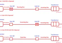
There is no import power or export power from the grid. The connected load requirement can be delivered to our Source alternator. At that time, the grid breaker in open/isolated condition. This condition frequently arrives due to the grid disturbance.
Rotor main field winding:
This is consisting of full copper winding with insulation (Normally class F type insulation). The cooling fan is attached to the rotor end side, in order to cool the alternators rotor and the stator coil. This is a very big topic, let see later…
Rotor Protection part: Rotor Earth Fault protection
The rotor earth fault protection is the only one protection for the alternator’s rotor. This is main protection for the rotor, it is considering of two stages such as stage 1 and stage 2. This is relay works under ohms’ law. Whenever the resistance is low there is current will be high. The first stage creates alarm in the annunciator panel, and the second stage makes tripping Signal to the alternator CB and turbine speed Governor control panel. In this you can do two kinds of setting, one is resistance setting and the current setting
Cooling System:
Forced cooling system. This system needs a separate cooling system. It is called auxiliary cooling system. The will call with the name of ACW. There is a separate motor feeds the water to the cooling tubes, the cooling tubes are monitored by water leakage detector.[wp_ad_camp_1]
Protection system:
There are so many protection systems are there to protect the alternator. Example: Over current, earth fault, IDMT, DMT, Voltage protection, Flux protection, etc.
Synchronization:
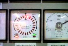
Synchronization can be done by completing three conditions:
- The grid voltage and Alternator voltage must be same
- The grid frequency and alternator frequency must be same
- The phase sequence must be same.
Export:
After Synchronization the power can be exported to the grid.



Thanks for the great manual
This is actually useful, thanks.