Basic Idea about transformer vector group
In theory of a three-phase transformer works like three equal and separated single-phase transformers (working separately with three phase system) with shared limbs. Here the magnetic circuit for the two outer limbs of the three phase transformer is lit bit longer than for the center limb of the same.
The output voltage transformation is determined by the ratio between the number of turns on the primary windings and secondary windings and assuming the even connection.
Based on this, it is theoretically possible to connect any pair of windings in a 3 phase transformer in the following pairs of combinations: Dd, Dy, Dz, Yd, Yy, Yz, Zd, Zyand Zz; of this, the first six, are the most commonly encountered ones in practice.
Here the
Y => Primary star connection
Y => Secondary star connection
D => Delta winding on Primary side
d => Secondary delta winding connection
Z => Primary Zig-Zag connection
Z => Secondary Zig-Zag connection
N => Primary connection Connected with neutral point
n => Secondary Zig-Zag connection
Numerical identity:
Here the numerical identity indicates the clock position of the phase displacement. It’s may be clock wise or anti clockwise. i.e
- Here the hour indicates phase displacement in angle. Because there are 12 hours on a clock, and a circle consists out of 360°, each hour (I mean one hour) represents 30°.Thus 1 = 30°, 2 = 60°, 3 = 90°, 6 = 180° and 12 = 0° or 360° and so on.
- The minute hand is set on 12 o’clock and replaces the line to neutral voltage (sometimes imaginary) of the HV winding. This position is always the reference point.
- Example:
- Digit 0 =0° that the LV phasor is in phase with the HV phasor
Digit 1 =30° lagging (LV lags HV with 30°) because the rotation is anti-clockwise. - Digit 11 = 330° lagging or 30° leading (LV leads HV with 30°)
- Digit 5 = 150° lagging (LV lags HV with 150°)
- Digit 6 = 180° lagging (LV lags HV with 180°)
Definition of transformer vector group:
Actually, The transformer vector group shows the phase difference between the primary and secondary sides of the transformer.
What is the use of a transformer vector group?
Basically transformer vector group is used to find the high voltage and low voltage windings arrangement of three-phase transformers. The three-phase transformer can be connected in various ways and the transformer’s connection is determined using its vector group.
The transformer’s vector group is depending on the following factor:
- Removing harmonics: The star winding of the three-phase transformer is used to reduce third harmonics.
- Parallel operations: To perform parallel operation All the transformer’s vector group and polarity should be same.
Let’s see the most commonly used transformer’s vector group is dYn11.
This is one of my power transformer’s vector group, which is 110 kV/11 kV. This is can be used for both operations such as step down and step up. In this,
Y => indicates primary winding high voltage side is connected as star winding
d => indicates secondary winding low voltage side is connected as delta winding
N => Indicates the primary star connection is connected with the ground.
11 => indicates the clock position which means the phase difference between the primary and secondary of the transformer. The 11 indicates that the low line voltage lag, high line voltage by 11 Χ 30° = 330° (considered one hour for 30 deg.) measured from higher voltage phasor in a clockwise direction.
See the picture for better understanding of vector grouping:
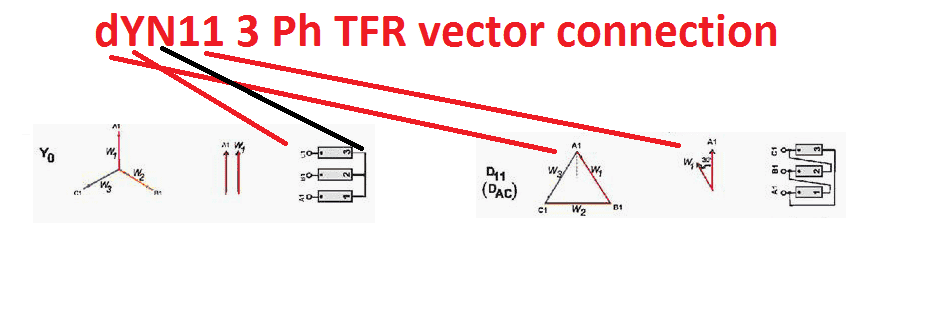
The below-mentioned diagram can be used for a better understanding of transformer vector grouping and its usage.
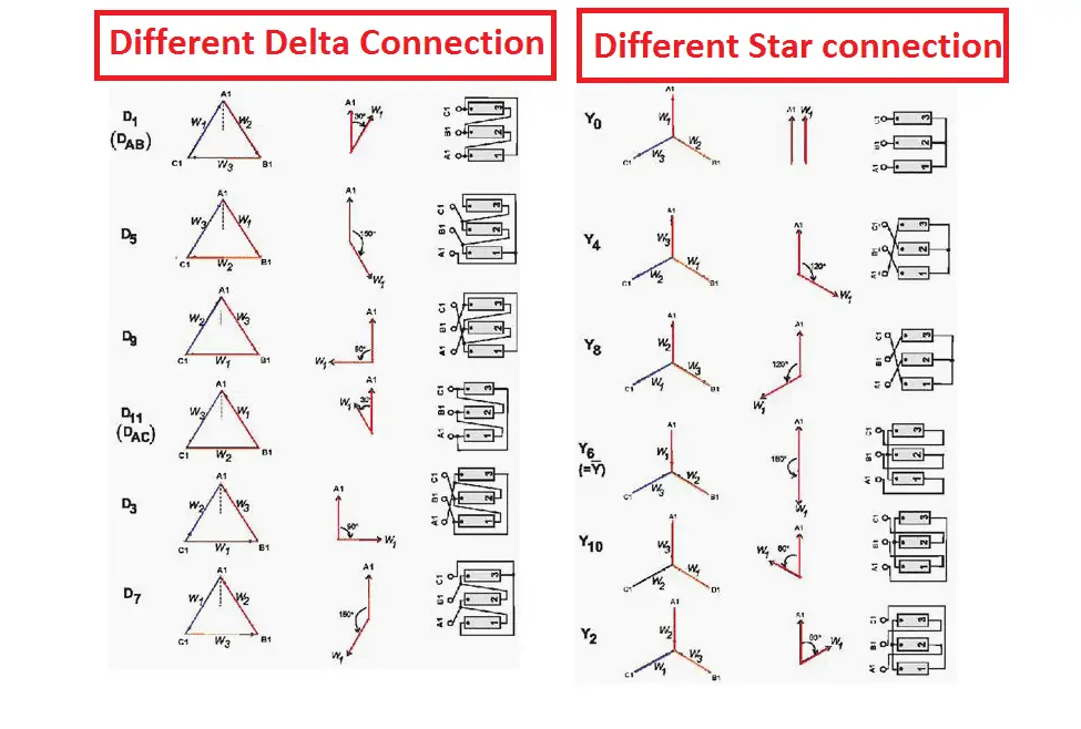
The phase-bushings on a three-phase transformer are marked either ABC, UVW or 123 (HV-side capital, LV-side small letters). Two winding, three-phase transformers can be divided into four main categories
| Group | O’clock | TC |
| Group I | 0 o’clock, 0° | delta/delta, star/star |
| Group II | 6 o’clock, 180° | delta/delta, star/star |
| Group III | 1 o’clock, -30° | star/delta, delta/star |
| Group IV | 11 o’clock, +30° | star/delta, delta/star |
The most commonly used number are 0, 6, 1, and 11 in the group reference number indicates the primary to secondary phase shift regarding the hours of the clock. For example,
0 deg => 0 deg phase shift. Which means primary high voltage side and low voltage side in the same phase
6 deg => 180 deg phase shift Which means Low voltage lags high voltage by 180 deg
1 deg => 30 deg. Low Voltage lags 30 deg with high voltage
11 deg => 330 deg. Low voltage lags 330 deg with high voltage.
Note: To perform the parallel operation, The three-phase transformer must have same vector group, Otherwise you will get the heavy short circuit.
For example:
A Y-Y winding transformer can be connected with another Y-Y or delta-delta transformer. But the same three phase transformer cannot be parallel with another delta-star or star-delta or any other clock displacement winding’s Transformer.
For simple understanding about three phase transformer vector group:
Significance of three phase transformer vector group:
The star or delta winding of the three phase transformer can be connected in six difference type of connection. To perform transformer’s parallel operation without seeing the winding connection, the manufacturer mentions the transformer’s vector grouping to avoid accidental faults.
Also it indicates the transformer’s winding, how its winding’s end connection is connected to output terminal.






say a few reason about installing two transformer with different vector grope if it make problem say the reason if not say the reason ?