Differential Relay working Function:
One of the most important protection in power system is differential protection. It is used to protect the electrical equipment against internal fault such as internal winding short circuit or bus bar phase to phase short circuit, inter turn short, winding puncture etc. It works under Kirchhoff’s current law. It stats that the algebraic sum of a node in a circuit is equal to zero. The differential relay can be defined as the relay operates when the phasor difference between the two or more electrical quantities exceed the pre-set value.
Types of differential relay:
- Current balance differential relay
- Voltage balance differential relay
- Biased differential relay or percentage differential relay
Current balance differential relay:
[wp_ad_camp_1]
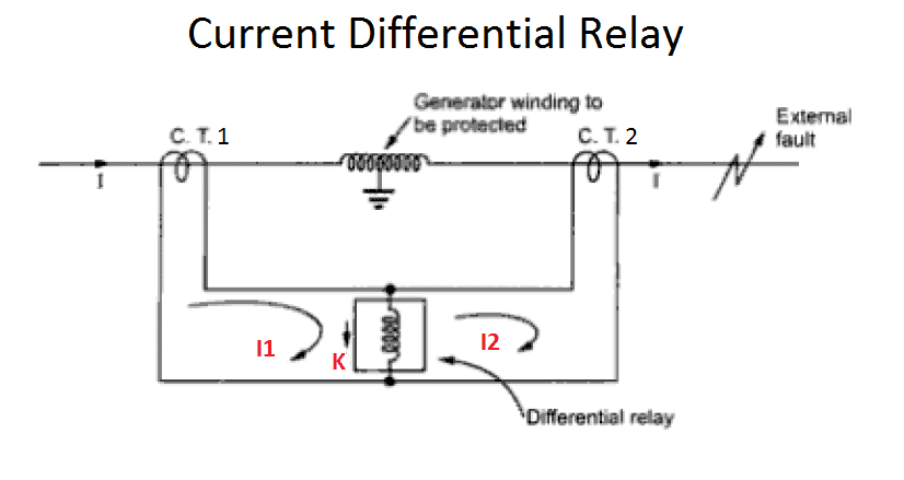
In current balance differential relay, the circuit current is a comparison quantity. Two current’s magnitude and phasor comparison takes place. Consider a circuit in the figure, two current I1 and I2 are Two CT’s output. The operating coil K is placed across the current transformer. Here during normal condition two current I1 and I2 have equal magnitude and phasor. Hence at a point A both cancels each other. Therefore, the current flow through the coil K is zero and the relay become in operative. During abnormal condition, the current I1 is not equal with I2. Then there is a current flow through the coil K, if the current flow through the coil k is exceed the preset value, then the relay operates the associated circuit breaker.
In three phase circuit two kind of CT configuration are made in differential protection one is high impedance differential protection and another one is low impedance differential protection.
High Impedance differential protection means the relay coils operates high voltage low current and low impedance differential protection the relay coil operates under high current with low output voltage.
Disadvantage of Current based differential relays:
- The CT connection are connected through a cable. Hence the cable impedance added. It creates slight different in the current through the relay coil. Also, the relay coil is more sensitive, change to nuisance tripping of the circuit even there is no fault.
- It needs additions stabilizing resistance in order to increase the relay stability.
- CT needs accurate ratio as well as burden.
Voltage Balance differential relay.
[wp_ad_camp_1]
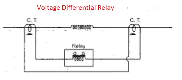
In this one over current relay is connected through the CT as shown in the figure. This is also called opposed voltage method. Under normal condition, the current I1 and I2 is equal in magnitude and phase. They cancel each other. The voltage balance is equally maintained. Under Fault condition, due to unbalance current in the circuit creates voltage unbalance in the over current coil. This cause voltage drop across relay and this drop operates the relay or associated circuit.
Also see:
- Bucholzz Relay Working Principle
- Calculate Stabilizing Resistor For High Impedance Differential Protection
- Difference Between Current Transformer & Voltage Transformer
- Distribution Transformer & Power Transformer
- Leakage Reactance of Transformer
- Percentage Differential Relay or Biased Differential Protection


![What is Normally Open & What is Normally Closed [Video Included] What is NO and NC](https://www.electrical4u.net/wp-content/uploads/2020/09/What-is-NO-and-NC-218x150.png)




I used to be able to find good information from your blog articles.