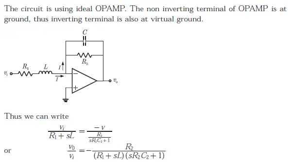
Q. 47 The OPAMP circuit shown above represents a
(A) high pass filter
(B) low pass filter
(C) band pass filter
(D) band reject filter
Answer: B
Explanation:

Q. 47 The OPAMP circuit shown above represents a
(A) high pass filter
(B) low pass filter
(C) band pass filter
(D) band reject filter
Answer: B
Explanation:
