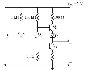
Q. 42 The circuit diagram of a standard TTL NOT gate is shown in the figure. the modes of operation of the transistors will be
(A) Q1 revere active; Q2 normal active; Q saturation; Q4 cut-off
(B) Q1 revere active; Q2 saturation; Q saturation; Q4 cut-off
(C) Q1 normal active; Q2 cut-off; Q cut-off; Q4 saturation
(D) Q1 saturation; Q2 saturation; Q saturation; Q4 normal active
Answer: (B)
Explanation:


