WHAT IS RECTIFIER
Many electronic gadgets like laptop, mobiles etc. works on DC supply. Hence AC supply is converted into required DC supply for proper functioning of this device. But how do we do it?
This task is done by the circuit called Rectifier.
Let’s first understand AC and DC signals.
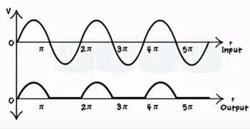
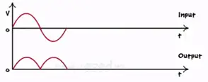
AC is the alternating current signal continuously varies in sinusoidal shape with respect to time. When it goes about zero line we get the positive magnitude of the signal is called positive half of the AC signal.
When the signal goes below zero line we get negative magnitude of signal referred to as negative half.
DC or direct current has the constant magnitude which is independent of time.
Let’s see how to convert varying AC signal into constant DC signal using rectifier circuits. Rectifier is two main types’
- Half wave rectifier
- Full rectifier
Rectifier circuits are made up of few basic components consider AC signal as input.
Transformer
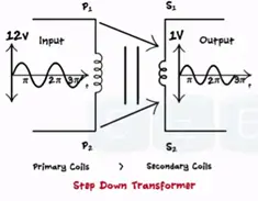
Every transformer ha two sides primary and secondary. Input is applied on primary and output is taken is secondary. Here we used step-down transformer. It’s called as step-down number of coils at primary is greater than the number of coils in secondary. The specification of transformer is given in terms of ratio. If the turns ratio in 12:1 then the transformer input signal 12 V to output signal volts.
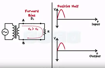
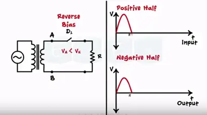
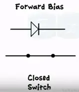
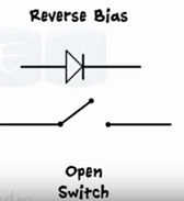
In rectifier diode acts as a switch. If the diode is connected to forward bias it acts as a closed switch. It is connected to reverse bias it acts as an open switch.
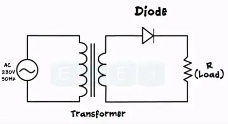
Working of half wave rectifier
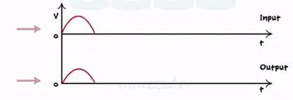
During the positive half of the input signal point A is the higher potential than the point B. hence anode of the diode receives more voltage than the cathode which makes the diode forward biased. Acts as a closed switch allows the current flow through it. Thus we obtain exact replica of input signal with low amplitude due to the step down transformer.
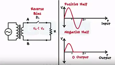
During positive half of the input signal point B is higher potential than point A. this makes the diode reverse biased. This acts as open switch and not allow current to flow.
Hence during the reverse bias mode we get “0” output.
We get rectification only half part of the input this circuit is called half wave rectifier.
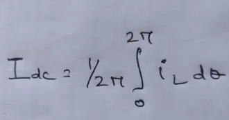
Mathematical analysis of half wave rectifier. Here we derive the expression for DC or average value of load current by (Idc).
Root mean square current value is denoted by (Irms) input voltage (Vdc) rectifier efficiency (ŋ ), ripple factor( R), peak inverse voltage(PIV), voltage regulation for calculating DC value of current waveform. We want to determine under the curve over one complete cycle. i.e. 0 to 2π divided by the base 2π.
Mathematically the current waveform is described as
iL = Imsinɵ for 0≤ ϴ ≤ π
iL = 0 (for the value for π ≤ ϴ ≤ 2π )
So that DC current is given by the equation
As the waveform divided into two parts we get the two integrals
Full wave rectifier
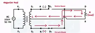
In full waveform rectifier we use a center tap transformer. This transformer has three terminals S1, S2 and C two are the secondary terminals third terminal is taken out exactly hence the name center tap transformer. The center terminal C is always connected to the ground. During positive half S1 has positive value, S2 has negative value as vice versa during negative half.
Full wave rectifier consists of two sets of diodes instead of one.
During the positive half of the input signal point A attains the positive half voltage and point b attains negative voltage. Thus diode D1 becomes forward bias and acts as a closed switch were diode D2 becomes R bias and acts as a open switch. During positive half current flows through diode D1 and follows the path S1 to point A. A to point D through diode D to E through load resistance RL then E back to point C producing same output as that of half wave rectifier.
But during the negative half the situation is reverse point B attains the negative value and point A becomes negative D2 becomes forward bias and acts as a closed switch, D1 becomes reverse bias and acts as an open switch. Hence current flows through the diode D2 only tracking the path S2 to point B and B to point D through diode D2 point D to E through load resistance Rt and point E back to point C as during the both the half’s current follows in the same path through the load i.e. point D to point E. We get the same positive output during the negative half also. As we get the output for full input signal. This rectifier is called fill wave rectifier.

