Inductor:
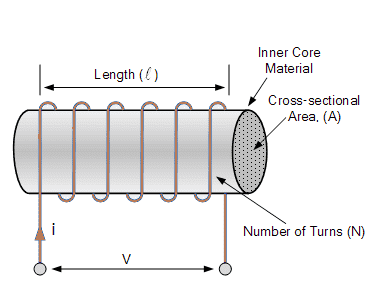
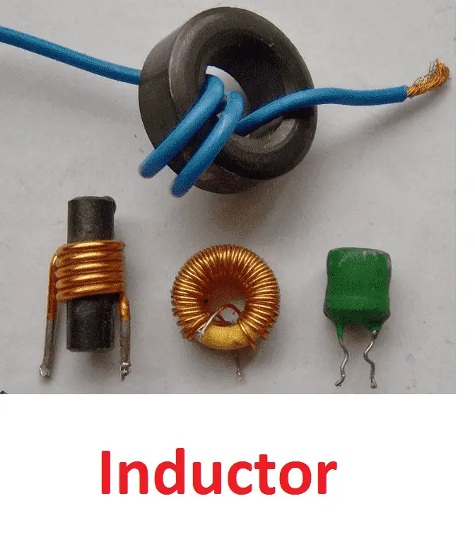
Inductor store energy in terms of magnetic field. It is a two terminal device, which is consisting of a coil wound around a core. Refer the diagram an inductor is having a coil with N number of turns. An Ideal inductor, the internal resistance of the coils is zero. But all inductors have its own property of opposing the flow of current. which is called as inductance reactance.
A similar to resistor and capacitor the inductor is also a passive component.
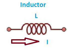
When metal wire is wounded in a circular manner we get a inductor. Symbol of inductor is shown in figure. It is represented by a letter L and its unit is Henry H.
Practically Henry becomes large unit. We use generally smaller units Milihenry (mh) and micro Henry (μh).
The materials on the coil are wounded is called core of an inductor. When coil wounded of the metal we get iron core inductor and there is no material and circular wingdings we get an air core inductor.
Inductor works only, in an Alternating Current circuit. In Direct Current circuits inductor acts as a short circuit path to the current. Due to this property, the transformer should not charge with DC Power supply. Also, another one important property of inductor (current through an inductor cannot be changed instantly) uses in VFD, a Filter circuit, SMPS, UPS, battery charges, Electric motor, and inductor is everywhere in the world etc.
Working of Inductor:
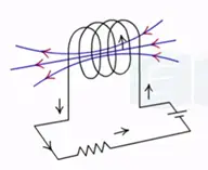
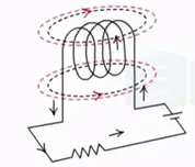
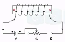
According to the magnetic effect of an electric current when a current passes through a coil or a conductor produces the magnetic field around that conductor. This forms a basic principle of a conductor.
The magnetic field produces flux around the conductor. This flux charges as the current flowing through the inductor.
According to faradays law EMF gets induced in a conductor whenever a flux linked with that conductor charges.
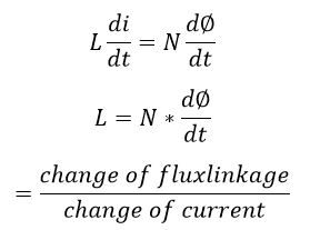
Let us consider a closed circuit, in an inductor, I is the current (flow of electron or charges), the inductor produces the flux pi, the inductor wound with N number of turns; According to faradays law due to rate of change of the flux linkages an emf gets induced in the coil. The emf induces without physical motion of the coil or flux the induced emf is called as self-induced emf. If the coil has N number of turns, then the total flux linked by N turns is equal to..
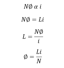
Hence the total flux linkages in an inductor is directly proportional to the current I, that is,
Here the proportional constant L is the inductance of the coil. The SI unit of inductance is Henry.
What is self Inductance:
The property of a coil which opposes any change in the current passing through it is called as self-inductance or only inductance.
L=Nɸ/I unit Henry (H)
Mutually Induced EMF
If the flux produced by one coil is linked with second coil and if the change in the flux produced by the first coil induces the emf in the second coil then such as emf is called as a mutually induced emf.
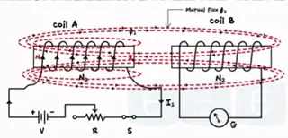
Consider two coils coil A and coil B and having N1 and N2 number of turns respectively. Current I1 flowing through the coil A producing flux ɸ1. Some parts of flux gets linked with coil B. which is called as a mutual flux ɸ2.
When we change the magnitude of the current flowing through the coil A by variable resistance the linked flux is ɸ1 and ɸ2 also charged. According to faradays law charge in the flux induces the emf in the coil.
Any charge in the current I1 induces the emf in coil B. this phenomenon is called mutually induced emf.
Let’s see the concept of back emf.
Inductor is a component that opposes the charge in the current flowing through it hence whenever a current flowing through a conductor charges inductor develops an emf. Amplitude of the emf is exactly equal to opposite to VL.
Amplitude of emf=-VL=-L*di/dt
This is known as back emf
Difference between inductor and inductance:
Inductor is the material which is used to establish the theoretically calculated value of inductance of the coils to the practical world, where the inductance is the value of the inductor.
Simply,
Inductor: Material
Inductance: Property of inductor, the value use to design a specific inductor.
[wp_ad_camp_1]
History:
The inductance was discovered by an American physicist, Joseph Henry in 1830 and Michal Faraday in separate continents, Actually, the first inductor was discovered by Michal Faraday. The symbol L for inductance, in honor of the physicist Heinrich Lenz. In the SI system, the measurement unit for inductance is the Henry, with the unit symbol H, named in honor of Joseph Henry, who discovered inductance independently of, but not before, Faraday.
Also see:History of Electrical Engineering
Units:
The unit of inductance is Henry, unit of current is Ampere, unit of flux is Weber.
Definition of one Henry:
An inductor produces 1 Weber for one ampere means the inductance value is one Henry.
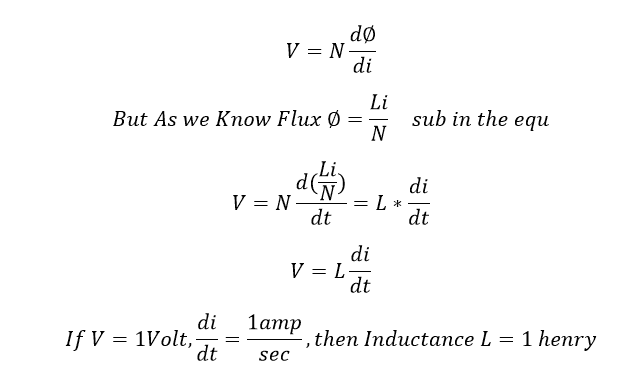
Suppose the varies with respect to time, then the magnitude of the magnetic flux also varies with respect to time. As per Faraday’s law of electromagnetic induction, the time-varying magnetic flux creates an induced voltage in each turn is equal to the derivative of the flux, hence the voltage V across N turns is,
Hence, a coil has an inductance of 1 Henry, if an emf of I volt is induced in the coil when the current varies uniformly at the rate of 1 amp/sec.
The voltage V appears across the terminals of the coil, and it tends to oppose the current entering the coil.
From the two voltage…
The flux is directly proportional to the current flowing across the conductor.
Also, the energy stored in an inductor is equal to..
Series and Parallel connection of an inductor:
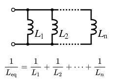
Inductor Parallel connection:
Inductors in a parallel configuration each have the same potential difference (voltage). To find their total equivalent inductance (Leq):
Inductors in series:
The current through inductors in series stays the same, but the voltage across each inductor can be different. The sum of the potential differences (voltage) is equal to the total voltage. To find their total inductance:
Types of inductors:
Inductors are divided into four types
- Coupled inductors
- Multi-layered inductor
- Ceramic inductor
- Moulded inductor
Coupled inductor
Coupled inductor exist magnetic flux that is dependent on other conductors to which they are linked. When mutual inductance is needed coupled inductors are often used. Transformer is a form of coupled inductor.
Multi-layered inductor
This inductor consists of layered coil wounded multiple times around the core. As a result of multiple layers and insulation’s between them. Multi-layer inductors high inductance level.
Ceramic core inductors
There are numerous kinds of cores and ceramic core inductors are unique having dielectric ceramic core i.e. it has very low distortion and hysteresis.
Moulded inductors
These inductors are moulded using plastic or ceramic insulation. They are used in circuit boards.
Also see:
- What Is Resistance? Resistive of the Resistor & One Ohm Resistance
- What is Resistor Resistance in series and Parallel Circuit
- AC DC Full Load Current Calculation Formula
- Active and Passive Components
- Basic Concept of DC Generator and Types of DC generator
Key points:
- The inductance value or the rate of change of current doubled the induced emf also doubled
- Inductor works under the faraday’s law of electromagnetic induction.
- Inductor do not allow the instant current changes.
- Inductance is the property of inductor to oppose the flow of current.
- The flux is produced in the inductor is directly proportional to current flow through it.
- Inductor works under AC power source; it creates short circuit path to the DC power source. Hence the inductor cannot be used in DC circuit.
Also see: What is Meant by Open Circuit
Self Inductance Vs Mutual Inductance:
Self Inductance is defined as the property of inductor which induces the emf in the same circuit due to changes in the current. example: torrid coil
Where mutual Inductance is defined as the emf induced in the other circuit by change in the current in the other circuit. Example: Transformer
Also see:
- Line Voltage to Phase Voltage Line Current to Phase Current Relationship
- Single Phase System vs Three phase System
- Types of Capacitors Based on Material Used
- What is Capacitance, Capacitor Series and Parallel Connection
- What is Capacitor Basic Concept Of Capacitor
- Why Capacitor and Inductor are used in Filtering Circuit
- Why capacitor is required for Single phase motor
- Why Capacitors Use As High Voltage Protection
- All Protection Relays Superb Explanation












![What is Arc Chute? Types, Working Principle [Video Included] arc chute working priciple](https://www.electrical4u.net/wp-content/uploads/2020/06/arc-chute-218x150.png)