Resistor:
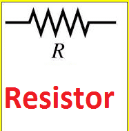
A resistor is nothing but opposition, It is the fundamental electronics component which use to oppose the flow of current or component or device or component designed to have a known value of resistance. The main purpose of resistor us to limit the current (flow of electron) in a particular circuit.
It comes in a variety of forms and you can purchase them as your wise, or even some using terminals to the very small surface mount components used in many electronics circuits today.
A resistor is one of the three fundamental passive circuit elements and as such cannot deliver power or store energy. Instead, resistors absorbed power that appears as heat (heater) and light (Light Emitting Diode).
Power in resistance is always positive regardless of voltage polarity and current direction. It just limits the current. In conductor small value of resistance always present.
Even though they all resist current flow, their other parameters mean that some types are more suitable for particular applications than others.
Types of resistor:
It is classified into two types. They are
- Fixed type
- Variable type
A fixed type is further classified into three types, they are
- Carbon composition type
- Wire wound type
- Metalized type
Fixed type
As per their name, the value of the resistor is fixed. Example: 11Ω, 14 Ω 164 Ω etc.
Carbon composition type.
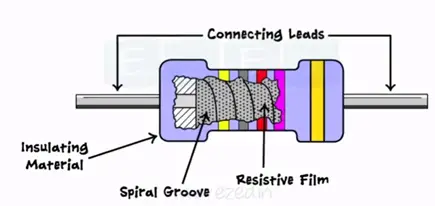
It is the most commonly used. It is made up of carbon clay composition with a plastic case coating surface. Hence it is called a carbon composition resistor. Leads are made up of tinned copper.
They are cheap and reliable and have high stability.
Wire-wound Resistor
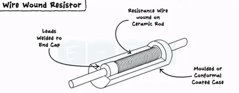
Wire wound resistor made by wounding of metal wire with nichrome around ceramic, plastic, fiberglass and of the wires is soldered or welded with two caps or rings attached to the ends of the core.
The assembly is protected with a layer of paint by modulated plastic or enamel. Coating baked at high temperatures.
Metalized resistor
It is a general-purpose resistor. It uses ceramic core coated with metal oxide. These resistors are electrically stable and reliable during high-temperature operation.
Variable resistor
The very common example of a variable resistor is the volume control knob or regulator of the fan.
The motion of the knob actually changes the resistance of the circuit and charges the level of the volume. Similarly, the motion of the regulator charges the speed of the fan.
It has three leads one is variable and the other two are fixed.
There are two types of variable resistors. They are
- Rheostat
- Potentiometer
Rheostat
It is two fixed leads and the other one is variable and made one end to another end. This lead moves from left to right. Its resistance moves from minimum to maximum. The rheostat is used in the laboratories for experimental purposes.
Potentiometer
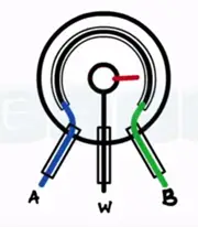
It has three leads A, B, and W and center lead are adjustable lead vary from end A to B. here R at end A is minimum and b is at maximum.
In the case of potentiometer also resistance varies in the same manner as seen in rheostat mix resistance to maximum resistance. The practical potentiometer as shown the most common example of a potentiometer is a regulator of the fan,
Colour coding:
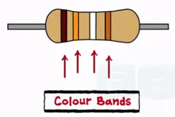
As a component resistor has different color bands printed on resistor which decides the value.
How to calculate the value of the resistance?
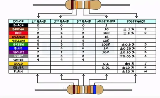
There are two types of resistors with four bands and live bands. Every color band has its own decimal value which starts significance and it’s obtained from the following table.
To remember this table and value for the color bands we follow the sentence.
“BB Roy of Great Britain has a Very Good Wife”
All capital letters represent the colors
Black Brown Red Orange Yellow Green Blue Violet Grey White
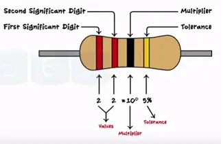
In the case of four band resistors 1st,2nd of left determine the decimal value 3rd band is the multiplier 4th band is for tolerance. Consider R with four bands.
Red, red, black and golden
From the tables, we get the values 2 for left and black for 0 and 5% for golden
The total value of the resistor is
22*10± 5%
22*1± 5%
22±5%Ω
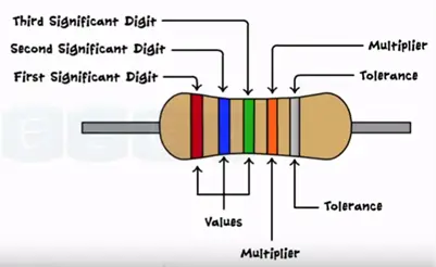
The only modification in five band resistors is the first three-color band determines the values and fourth band for multiplier and fifth band for tolerance.
Red blue green orange silver
265*10³ ±10%
265KΩ±10%
Characteristics of Resistor
The characteristics of a resistor are the resistance value power dissipation or power rating.
When an electrical current passes through the resistor electrical energy is lost by the resistor in the of heat. Greater the current flow the hotter the resistor will get this known as resistor power rating.
Power Dissipation in a resistor:
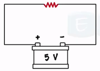
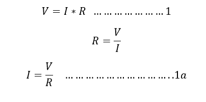
As we Know from ohm’s law, V is the input voltage and I is the current flowing through the resistor and R is the resistance circuit.
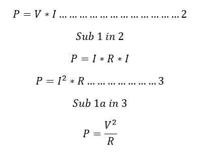
Power dissipation in the circuit
Here P is the power dissipation in the circuit. And the power rating normally, mentioned in Watts
The power rating of a resistor:
When the resistor manufacturer design a resistor, all the resistor has the power ratings which is the maximum power that resistor can absorb the power with safe operating limit, beyond that the resistance might be damaged.
Example:
2 Watts resistor means; it consumes 2 watts per hour.
Different resistance connection:
You can modify or change the total resistance value of the circuit by adding the different values of resistors in series or parallel with the circuit. Let see how series or parallel connection changes the equivalent resistance of the circuit.
Resistor series connection:
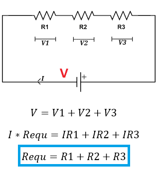
Refer the diagram, here the resistor R1, R2 and R3 are connected in series, Requ is the equivalent resistance of the circuit and the V1, V2, and V3 are the voltage drop across the resistor, V is the input voltage and the current I is flowing through all the resistor.
Apply Kirchhoff voltage rule.
Here the equivalent resistance of the circuit is equal to Sum of all individual resistance of the circuit which all connected in series each other. You can add an unlimited number of connections in the same way and you can calculate equivalent resistance in the same way.
The resistor in parallel Connection:
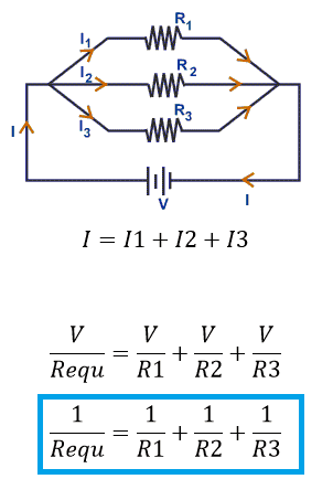
Refer the diagram, here the resistance R1, R2 and R3 are connected in parallel, Requ is the equivalent resistance or sum of all resistance of the circuit.
V is the voltage drop across the resistor, V is the input voltage and the current I1, I2 and I3 are flowing through the individual the resistance R1, R2, and R3.
I am the circuit total current, apply Kirchhoff’s current rule.
Note: Voltage in a parallel circuit is equal to the applied source voltage. Hence V input voltage is equal to the Voltage across the all individual resistor.
Reciprocal of equivalent resistance is equal to a sum of reciprocal of an individual resistance value of the circuit.







![What is Arc Chute? Types, Working Principle [Video Included] arc chute working priciple](https://www.electrical4u.net/wp-content/uploads/2020/06/arc-chute-218x150.png)