What is Summation Current Transformer:
First, current transformer is nothing but a step-up transformer which is used to convert high primary current into less current typically 5 to 1 Amps. It works under faraday’s law of electromagnetic induction. Generally, it is called as in the short form of CT. It is used to sense the line current. The output of the current transformer is given to the metering or protecting circuits. Here, the current transformer is used one per one phase. Hence to get three phase output we should use three transformers. In this case, to get the current value of the multiple feeder we should use more number of CTs. To avoid these the summation current transformers are used.
Definition for summation current transformer:
The output from the multiple current transformer is given to the single transformer, which converts multiple output into single output. It just reduces the metering complexity, installation of multiple equipment cost, wiring cost etc.
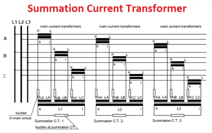
Please refer the diagram
[wp_ad_camp_1]
The main CT output from the various feeder is given to the common transformer. The sum of the all main transformer is equal to the output of the summation current transformer.
How to calculate burden for the summation CT:
First, what is Burden? Burden is nothing but a total VA output of the transformer. In our diagram, 3 main CTs are such as
CT1: 400/1 A, 10 VA
CT2: 200/1 A, 5 VA
CT3: 100/1 A, 3 VA
Then the summation transformer VA is equal to 10+5+3 VA= 18 VA or higher than 18 VA and the ratio should be of 700/1A
Note: All the transformer should have same secondary current, otherwise we cannot get accurate result from summation CT.
In case of absence of single Current transformer in the source side you should not make short on the terminal where the CT is not available. You keep the connection as its.
The CT ratio can be adjusted in the meter side as per the number of CT’s ratio.





![What is Arc Chute? Types, Working Principle [Video Included] arc chute working priciple](https://www.electrical4u.net/wp-content/uploads/2020/06/arc-chute-218x150.png)
