Distance Protection Relays Working Principle:
In last study we have discussed about only current or voltage based relay. Now we are going to discuss about current and voltage based relay. These relays are called as distance protection relays. The relay operation is purely depending upon the magnitude of the circuit current and voltage, typically the ratio of the circuit to be protected is calculated. The ratio of Voltage to current is called impedance. Here the prefix word distance mentions that impedance is nothing but an electrical measurement of distance along a transmission line. The relay measures the ratio of voltage and current. The ratio is less than a predetermined value, the relay trips the circuit breaker. The distance protection relay is also called as ratio relay.
Dependent on the ratio of V and I the distance relays are classified into three types
- Impedance (Z) relay.
- Reactance relay (X)
- Admittance (Y) or Mho relay
Impedance Relay
The impedance relay works based on the circuit quantities such as voltage and current. In this relay, there are two elements, the one produces a torque proportional to current while the other produces a torque proportional to voltage. The torque produced by the current element is equalized by the torque produced by the voltage element. The current element produces operating torque and voltage element produce the opposite torque to the current element. In other words, the torque produced by the voltage element is said to be negative torque.
Voltage reference is taken from the potential transformer and the current reference is taken from the current transformer. The section AB of the line is protected zone which is impedance of line. Under normal conditions, the ratio of voltage V and current I is constant which is denoted as Z. The relay is inoperative under this condition.
[wp_ad_camp_1]
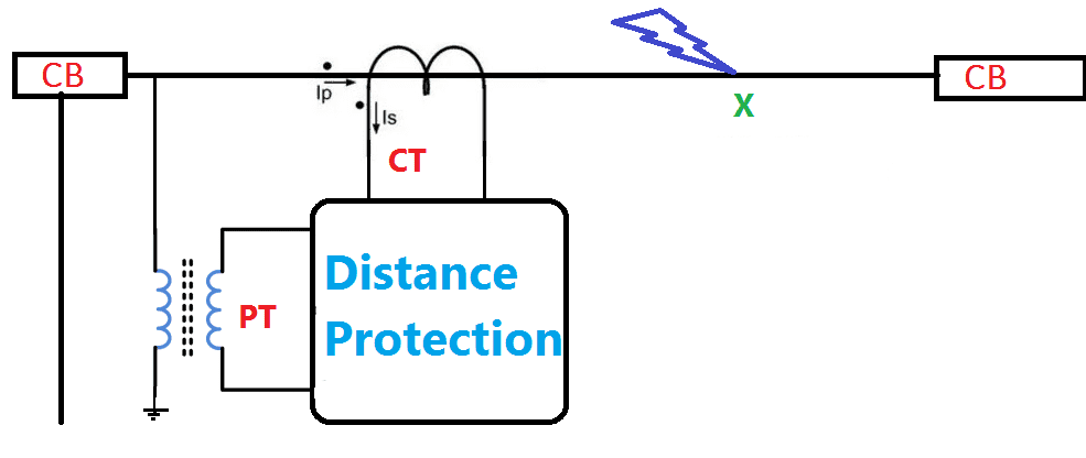
When the fault occurs at point X in the protected zone then the voltage drops while current increases. Thus the ratio of V/I. the impedance reduces. This is the impedance of line between relay located and the faulty point X. So when the impedance reduces than its predetermined value, the distance protection trips circuit breaker.
Also see:
- Bus Bar Differential Protection or Circulating Current Protection
- Directional Over Current & Non Directional Over Current Protection Working Principle
- Distance Protection Working Principle & Fault Location Detection
- Neutral Voltage Protection -59GN- 95% stator Earth fault protection
Torque Equation
Consider The circuit current I, Voltage V, T operating torque. The positive torque is directly proportional to I2 and the negative torque is directly proportional to the voltage element V2.
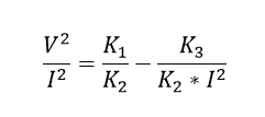
Let control spring effect produces a constant torque of –K3, Hence the torque equation becomes,
where K1. K2, are the constants,
At the balance point, when the relay is on the verge of operating, the net torque is zero hence we can write,
Divide By K2 I2 on both sides..
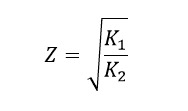
As We Know The ratio of voltage to current is called impedance. It is denoted by Z
Apply it on the above equation
Neglect the spring constant as it is absence in practical case. Hence K3=0
[wp_ad_camp_1]
Hence the ratio of V/I is constant at normal operating condition.
Also see:
- Restricted Earth fault Protection 64R
- Reverse Power Protection Working Principle -32R
- Rotating Diode Failure Relay Working Principle
- SOTF Relay Working Principle – Switch On To Fault protection
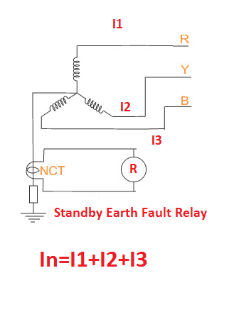
- Standby Earth Fault Relay Operation 51N
- Star Delta starter wiring diagram with Full Explanation
- Sweep Frequency Response Analysis -SFRA Test Procedure
- Symmetrical Faults & Unsymmetrical Faults
How Distance Protection Detects the Fault location:
From the above V/I ratio, for the particular fault the impedance is constant. But The value of the ratio changes according to the fault location changes. Also the fault is nearer to relay, this ratio of the V/I will be low and as fault position moves away from the relay the ratio becomes higher and higher. So it can be installed to operate for particular location to be protected and After conducting relay adjustments for the particular location, it is inoperative beyond that section.
Also see:
- PT Fuse Failure Relay Working Principle VTFF
- Voltage Restrained Over Current relay Basic concept -51VR VOC
- What is The Use Of Knee Point Voltage
- What is Through Fault
- Why CT secondary should not Open condition- Live Test Demo
- Why DC Voltage is preferred for Control circuit?
- Why Does Bird Not Get Shock on Transmission lines?
- Why Earth Pin is Plastic Thicker and Longer
- Why Earthing Transformer are used
- Why in India 11kV, 22kV, 33kV, 66kV, 132kV…
- Why India has 50 Hz Power System and US has 60 Hz 110 Volts Power System
- Why induction motor Takes high starting current
- Why Inductors Use In Filtering Circuit and VFDs
- Why is Battery United AmpsHour AH
- Why Lighting Transformer Used for Lighting Loads
- Why line chokes are used in VFD
- Why Permanent magnet generator (PMG) poles are high
- Why PT and CT Terminals are Star Connected
- Why Slip ring Induction motor is preferred for High starting Torque application
- Why Star delta starters are preferred for higher HP motor
- Why Tertiary Winding is used in transformer?
- Why transformer Rating in KVA exact answer
- Why VFD duty motor Frame size come in higher size
- Why we should not give dc supply to Transformer
- Why Zig-Zag Winding Transformer Used







![What is Arc Chute? Types, Working Principle [Video Included] arc chute working priciple](https://www.electrical4u.net/wp-content/uploads/2020/06/arc-chute-218x150.png)
